26
Quick Start Guide
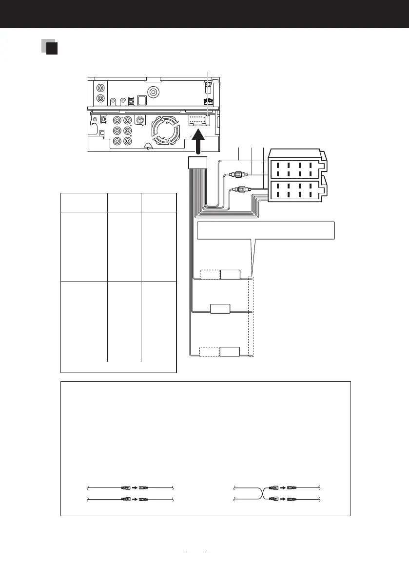
Connecting wires to terminals
Pin Numbers for
ISO Connectors
Cable Color Functions
External Power
Connector
A-4 Yellow Battery
A-5 Blue/White Power Control
A-6 Orange/White Dimmer
A-7 Red Ignition (ACC)
A-8 Black Earth (Ground)
Connection
Speaker Connector
B-1 Purple Rear Right (+)
B-2 Purple/Black Rear Right (–)
B-3 Gray Front Right (+)
B-4 Gray/Black Front Right (–)
B-5 White Front Left (+)
B-6 White/Black Front Left (–)
B-7 Green Rear Left (+)
B-8 Green/Black Rear Left (–)
*Speaker Impedance: 4-8 Ω
Fuse (10A)
1
2
3
4
5
6
7
8
1
2
3
4
5
6
7
8
P.CONT
ANT.
CONT
MUTE
REMOTE CONT
REMOTE INPUT
STEERING WHEEL
Accessory 1
A B
C
C: Red
(Ignition wire)
A: Black
(Ground wire)
B: Yellow
(Battery wire)
Connecteithertothepowercontrol
terminalwhenusingtheoptional
poweramplifier,ortothepower
terminalfortheboosteramplifier
ofthefilm-typeorshortpoletype
antenna.
Ifnoconnectionsaremade,donotletthe
wirecomeoutfromthetab.
Connecttotheterminalthatis
groundedwheneitherthetelephone
ringsorduringconversation.
Tousethesteeringwheelremote
controlfeature,anexclusiveremote
adapter(notsupplied)thatmatches
yourcarisrequired.
Blue/White (Power
control/ Antenna
control wire)
Brown (Mute
control wire)
Light Blue/Yellow
(Steering remote
control wire)
2
WARNING for Connecting the ISO Conncetor
ThepinarrangementfortheISOconnectorsdependsonthetypeofvehicleyoudrive.Make
suretomaketheproperconnectionstopreventdamagetotheunit.Thedefaultconnection
forthewiringharnessisdescribedin(1)below.IftheISOconnectorpinsaresetasdescribed
in(2),maketheconnectionasillustrated.Pleasebesuretoreconnectthecableasshown(2)
belowtoinstallthisunittotheVolkswagenvehiclesetc.
(2)
Thered(A-7pin)ofthevehicle’sISO
connectorisconnectedtotheconstant
powersupply,andtheyellow(A-4pin)is
linkedtotheignition.
(1): Default setting
Thered(A-7pin)ofthevehicle’sISO
connectorislinkedwiththeignition,and
theyellow(A-4pin)isconnectedtothe
constantpowersupply.
Red (Ignition cable)
Unit Vehicle
Yellow (Battery cable) Yellow (A-4 pin)
Red (A-7 pin)
Red (Ignition cable)
Unit
Vehicle
Yellow (Battery cable) Yellow (A-4 pin)
Red (A-7 pin)
 Loading...