User Manual
SUPM1
page 32 of 94© KEYMILE December 2015 EN/LZTBU 372 129/1 RC
94
Installation
4.7 Connections and Cables
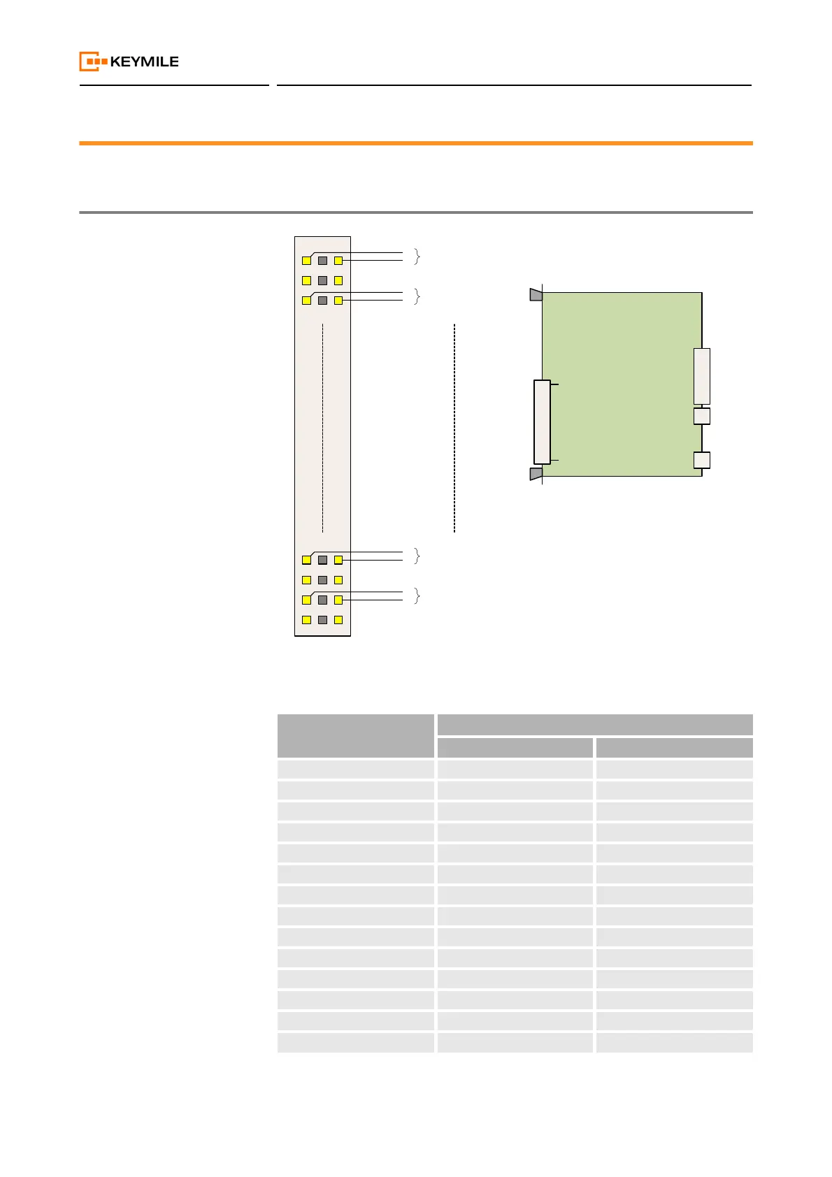
4.7.1 Front Connector of the SUPM1 Unit
Figure 6: Pin-out of the SUPM1 front connectors, front view
Table 27: SUPM1 front connector pins
PSTN port Connector pin for
signal a signal b
1 2c 2a
2 4c 4a
3 6c 6a
4 8c 8a
5 10c 10a
6 12c 12a
7 14c 14a
8 16c 16a
9 18c 18a
10 20c 20a
11 22c 22a
12 24c 24a
13 26c 26a
14 28c 28a
1
32
Connector positions
on the unit
Front
Connector
Backplane
Connectors
a b c
32
b
a
PSTN port 16
31
2
b
a
PSTN port 1
1
30
b
a
PSTN port 15
3
4
b
a
PSTN port 2