User Manual
SUPM1
page 48 of 94© KEYMILE December 2015 EN/LZTBU 372 129/1 RC
94
Functional Description
5.8 Input and Output Level
For each subscriber port the relative input level and relative output level of
the analogue signal can be configured.
In the digital network the relative level is at 0 dBr according to ITU-T G.101,
i.e. you effectively configure directly the relative levels at the analogue port.
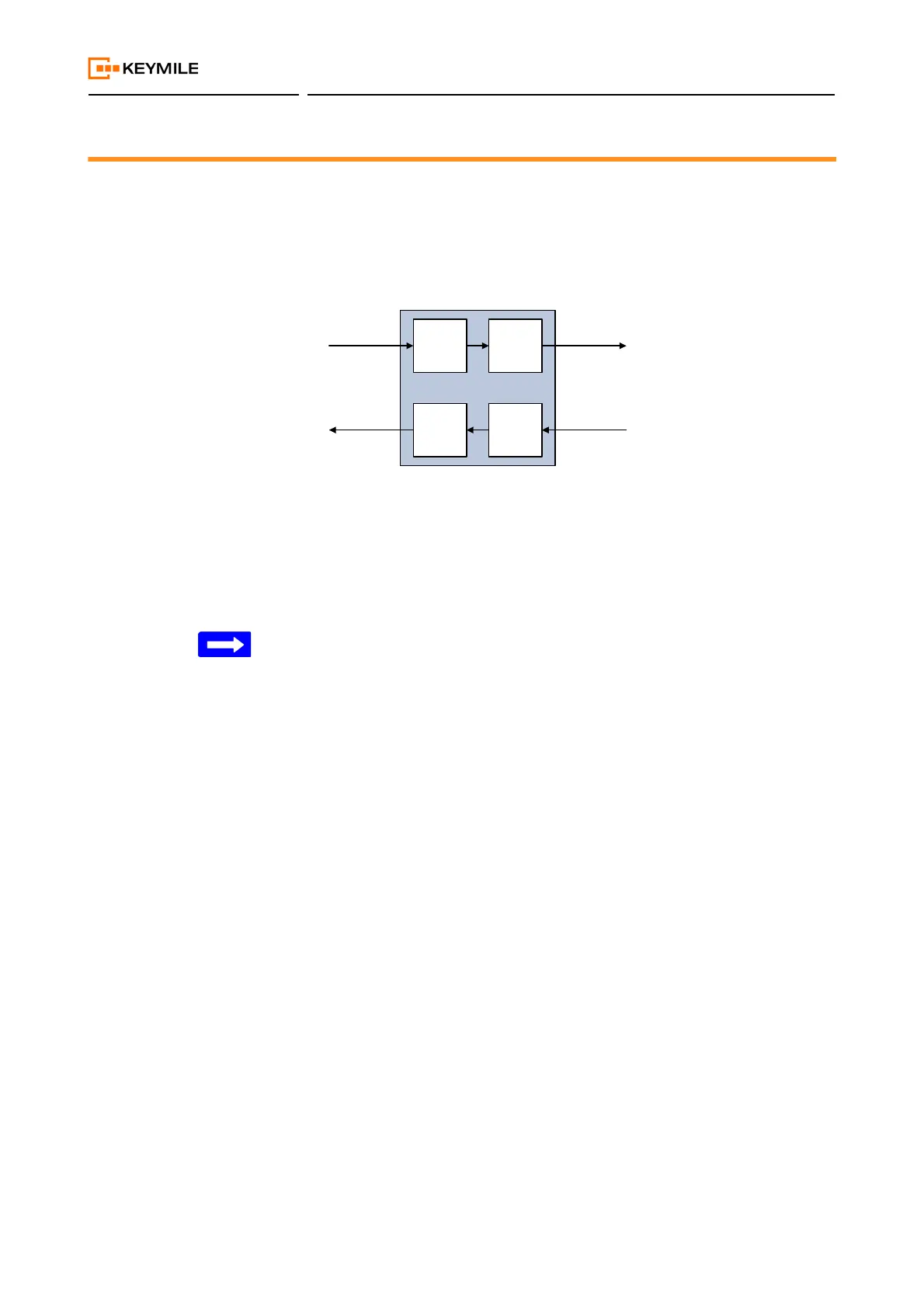
The following figure shows the relative levels, and in italic also the absolute
levels.
Figure 14: Level configuration on input and output directions
The values in italic are examples of absolute levels. With the shown configu-
ration you have in upstream direction a gain of 2 dB and in downstream
direction a loss of 6 dB.
The default levels, 0.0 dBr for input and -7 dBr for output levels, fit most
applications.
The absolute output level should always be at least 1 dB below the absolute
input level in order to eliminate any echo or instability of the subscriber inter-
face.
Note that the theoretical load capacity of a PCM A-law coded signal is
+3.14 dBm0. With a relative level of 0 dBr, the maximum absolute level is
therefore 0 dBr + 3.14 dBm0 = 3.14 dBm.
Analogue
Signal
Analogue
to digital
conversion
Input
Level
setting
-2 dBr
Digital to
analogue
conversion
Output
Level
setting
-6 dBr
-2 dBr
-12 dBm
-6 dBr
-14 dBm
0 dBr
-10 dBm
0 dBr
-8 dBm
PCM
Signal