User Manual
SUPM1
page 47 of 94© KEYMILE December 2015 EN/LZTBU 372 129/1 RC
94
Functional Description
5.7 Line Impedance Selection
The hardware of the SUPM1 unit is prepared to comply with many national
requirements concerning the line impedance. The line impedance parame-
ters can be configured with the element manager.
The line impedance is selected from a list according to the national require-
ments. The following impedances are implemented:
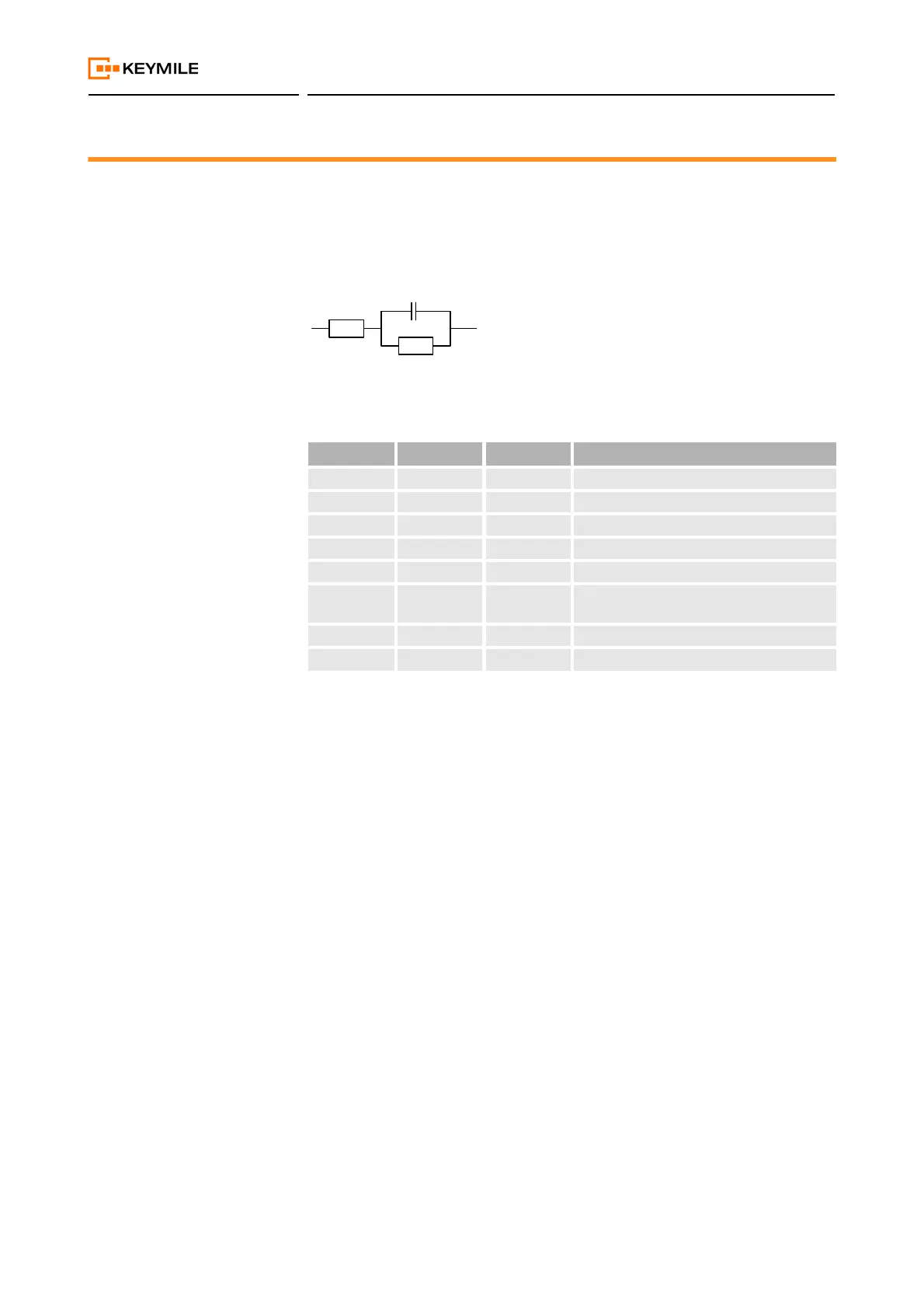
Figure 13: a/b impedance
The voice impedance should match the impedance of the connected termi-
nals. If the impedances don't match then the relative levels don't match with
the defined values and the subscriber line interface can become unstable.
If you don't find your impedance in the list, please contact the KEYMILE
Technical Support or your local KEYMILE customer support.
Table 34: Line impedance
R
S
[Ω] R
P
[Ω] C
P
[nF] Country example
900 A-law 0 0 Inter exchange impedance, ANSI
600 A-law 0 0 Standard real impedance
600 u-law 0 0 USA
200 680 100 China
370 620 310 UK
220 820 115 Standard European complex impedance,
e.g. for Germany etc.
300 1000 220 UK BT
270 750 150 ETSI definition