Keyscan Inc. – Technical Guide (PC109x - 07.15)
Note
If the NETCOM2 is mounted in the metal enclosure, the shield of the serial cable may be connected to
GND as shown. If the NETCOM2 is mounted outside the metal enclosure, the shield must be insulated and
connected directly to the metal enclosure ground lug. See Grounding Communication Cable Shield.
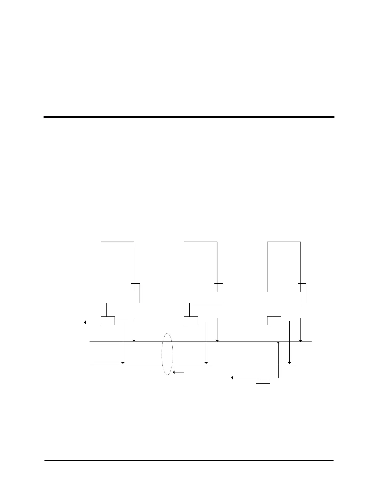
CIM Communication
The Communication Interlink Module (CIM) is used to establish PC to ACU and ACU to ACU communication
when multiple access control units are installed on a communication bus. The CIM uses highly reliable CAN Bus
architecture on CAT 5 cable with two (2) twisted pairs. The CIM modes of communication are as follows on the
CAN Bus:
CAN Bus 1 (required) - PC to ACU main communication
CAN Bus 2 (optional) - ACU to ACU communication for global functions (i.e. global anti-pass back, global
time zones, and global I/Os)
CAN Bus 2 - CIM to CIM communication for CIM hardware control and monitoring and Keyscan’s reverse
network communication
Keyscan recommends CAN Bus 1 and CAN Bus 2 are connected on all CIM units.
Figure 77 – CIM Overview
CIM 1
CIM n
ACU 1
* serial
or
network
connection
CAN Bus 1
ACU 2 ACU n
CIM 0
Refer to BPS/CAN Bus
Distance chart for
maximum bus distances.
CAN Bus 2
CAT5 - 2 twisted pairs
1 CIM as Global
Master
(least busy ACU)
optional
CIM link
to network
* CIM 0 is the unit with the
serial or network connection
which can be anywhere on
the CAN Bus. Only one CIM
can be designated as CIM 0.
Control
Board
Control
Board
Control
Board
PC109x
PC109x
PC109x
KI-00261E-07-12