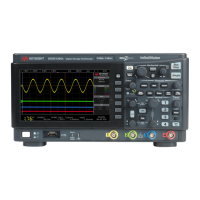
Do you have a question about the Keysight Technologies InfiniiVision MSO-X 3024A and is the answer not in the manual?
Guide on how to connect oscilloscope probes to the device under test.
Procedure to match probe characteristics to the oscilloscope channel for accuracy.
Adjusts the sweep speed and time per division for waveform viewing.
Controls the horizontal position of the trigger point and waveform data.
Enables split-screen view for detailed analysis of specific waveform sections.
Controls the vertical sensitivity (volts/division) of analog channels.
Selects input coupling mode (AC, DC, or Ground) for analog channels.
Accesses the Waveform Math Menu to perform calculations on signals.
Applies functions like differentiate, integrate, or FFT to analog input channels.
Stores current waveforms for later comparison against other signals.
Instructions for connecting digital probes for mixed-signal analysis.
Captures and displays digital signals alongside analog waveforms.
Lists available hardware-accelerated serial protocol decode licenses.
Sets the voltage threshold for analog channel edge detection.
Triggers on a specified edge slope and voltage level of a waveform.
Manages the oscilloscope's acquisition process, start, stop, and single shots.
Places and adjusts horizontal/vertical cursors for custom measurements.
Selects and displays automatic waveform measurements.
Automatically generates a mask from a known good waveform.
Selects waveform types like Sine, Square, Ramp, Pulse, Arbitrary.
Saves instrument setups, screen images, and waveform data to storage.
Configures remote control interfaces like USB, LAN, and GPIB.
Connects to the oscilloscope's built-in web server for remote control.
Configures the oscilloscope to capture and decode CAN signals.
Configures the oscilloscope to capture and decode LIN signals.
Configures the oscilloscope to capture and decode FlexRay signals.
Configures the oscilloscope to capture and decode I2C signals.
Configures the oscilloscope to capture and decode SPI signals.
Configures the oscilloscope to capture and decode I2S signals.
Configures the oscilloscope to capture MIL-STD-1553 signals.
Configures the oscilloscope to capture ARINC 429 signals.
Configures the oscilloscope to capture UART/RS232 signals.
| Brand | Keysight Technologies |
|---|---|
| Model | InfiniiVision MSO-X 3024A |
| Category | Test Equipment |
| Language | English |


