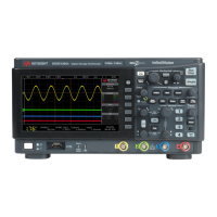
Do you have a question about the Keysight Technologies InfiniiVision MSO-X 3014A and is the answer not in the manual?
Details power requirements and the procedure for turning the oscilloscope on.
Steps for connecting oscilloscope probes to the device under test.
How to change the horizontal scale (sweep speed) to adjust time/div settings.
How to set the vertical sensitivity (volts/division) for a channel.
Applying transform functions or filters to arithmetic operations on analog channels.
Procedure to save analog channel or math waveforms to internal reference locations.
Steps for connecting digital probes to the device under test, including power considerations.
Lists available hardware-accelerated serial decode options and their corresponding licenses.
Adjusting the intensity of displayed waveforms to enhance visibility of signal details and noise.
Configuring waveform persistence to update display with new acquisitions or erase previous ones.
How to adjust the trigger level for analog channels using the Trigger Level knob.
Using the Force Trigger key to acquire data when trigger conditions are not occurring.
Identifying triggers by slope and voltage level on a waveform.
Selecting between Auto trigger mode (default) and Normal trigger mode.
Using the Run/Stop and Single keys to control the oscilloscope's acquisition system.
Choosing acquisition modes like Normal, Peak Detect, Averaging, or High Resolution.
Dividing oscilloscope memory into segments to capture multiple infrequent trigger events efficiently.
Using horizontal (X) and vertical (Y) cursors to measure custom voltage, time, phase, or ratio.
Procedure to make automatic measurements on waveforms using the Meas key.
Defining vertical levels for taking measurements on analog or math waveforms.
Creating a mask automatically from a golden waveform to define compliance parameters.
Provides 3-digit voltage and 5-digit frequency measurements using analog channels.
Step-by-step guide to activating and configuring the digital voltmeter for measurements.
Accessing the Waveform Generator Menu to select and enable output of various waveform types.
Opening the Edit Waveform Menu to define or modify arbitrary waveform shapes.
Procedures for saving oscilloscope setups, screen images, or acquired data to memory or USB.
Loading previously saved setups, masks, or waveform data back into the oscilloscope.
Connecting a printer and printing the current oscilloscope display.
Configuring remote access and control via USB, LAN, or GPIB interfaces.
Establishing a LAN connection for network access, web interface, and remote control.
Connecting the oscilloscope to a LAN or PC to access its web interface.
Gaining access to the Browser-Based Remote Front Panel and SCPI Command window.
Setting a password to restrict remote access to the oscilloscope's configuration and operation.
Provides detailed specifications and characteristics for the oscilloscopes.
Steps to connect to a CAN signal and specify source, threshold, baud rate, and sample point.
Configuring CAN triggers based on frame types, errors, or data values.
Setting up the oscilloscope to capture and decode CAN bus signals.
Steps to connect to a LIN signal and specify source, threshold, baud rate, and sample point.
Configuring LIN triggers based on sync break, frame ID, or data.
Setting up the oscilloscope to capture and decode LIN bus signals.
Connecting to a FlexRay signal and specifying source, threshold, baud rate, and bus type.
Setting up triggers for FlexRay frames, errors, or events.
Connecting to I2C signals and specifying source, threshold voltage levels for SDA and SCL.
Setting up I2C triggers for conditions like start/stop, acknowledge, or EEPROM data read.
Connecting to SPI signals and specifying clock, MOSI, MISO, and framing signal parameters.
Setting up SPI triggers based on data patterns, chip select signals, or clock edges.
Connecting to I2S signals and specifying source, threshold levels, word size, and alignment.
Setting up I2S triggers based on data values, qualifiers, or bus configuration.
Connecting to MIL-STD-1553 signals and specifying source, high/low trigger thresholds.
Configuring MIL-STD-1553 triggers for data word start/stop, command/status, or errors.
Connecting to ARINC 429 signals and specifying source, threshold, speed, and signal type.
Setting up ARINC 429 triggers for word start/stop, label, errors, or bits.
Connecting to UART/RS232 signals and specifying source, threshold, parity, baud rate, and bit order.
Setting up UART/RS232 triggers for Rx/Tx start/stop bits, data bytes, or parity errors.
| Bandwidth | 100 MHz |
|---|---|
| Analog Channels | 4 |
| Digital Channels | 16 |
| Form Factor | Benchtop |
| Vertical Resolution | 8 bits |
| Timebase Accuracy | ±20 ppm |
| Interface | USB, LAN, GPIB (optional) |
| Display | 8.5-inch |
| Connectivity | USB, LAN |
| Input Impedance | 1 MΩ |
| Trigger Types | Edge, Pulse Width, Serial |
| Power Requirements | 100-240 VAC, 50/60 Hz |
| Waveform Update Rate | 1, 000, 000 waveforms/sec |


