Keysight S5040A Open RAN Studio Player and Capture Appliance User’s Guide 45
Getting Started 2
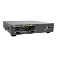
LED Indicators
During normal operation, the Tx1 - Tx4 and Rx1 - Rx4 LEDs indicate status
of the adjacent transceiver.
If the 10G/25G QSFP modules are plugged into QSFP port 1, the Tx1/Rx1
LEDs indicate the following:
• Off – QSFP is not plugged in or recognized
• Amber – Tx (or Rx) is set for 10G
• Green – Tx (or Rx) is set for 25G
• Red – no connection
• Amber or green blinking: packets are being received (Rx) or transmitted
(Tx) at the specified bit rate.
If an M-plane connector is plugged into QSFP port 3, Tx and Rx will only be
Green, but indicating a speed of 1Gbps, which is the only speed that the
M-plane connector supports.
Table 11 indicates the LED state for each Tx and Rx.
Table 11 Tx / Rx LED conditions
LED condition TX RX
Off QSFP unplugged QSFP unplugged
Red, solid uninitialized uninitialized or cable not connected (if detectible)
Amber, solid initialized, low speed initialized, low speed
Amber, blinking low speed activity low speed activity
Green, solid initialized, high speed initialized, high speed
Green, blinking high speed activity high speed activity