6-6 July 2004
Argonite
®
Engineered Fire Suppression System
38-KFSARG-000
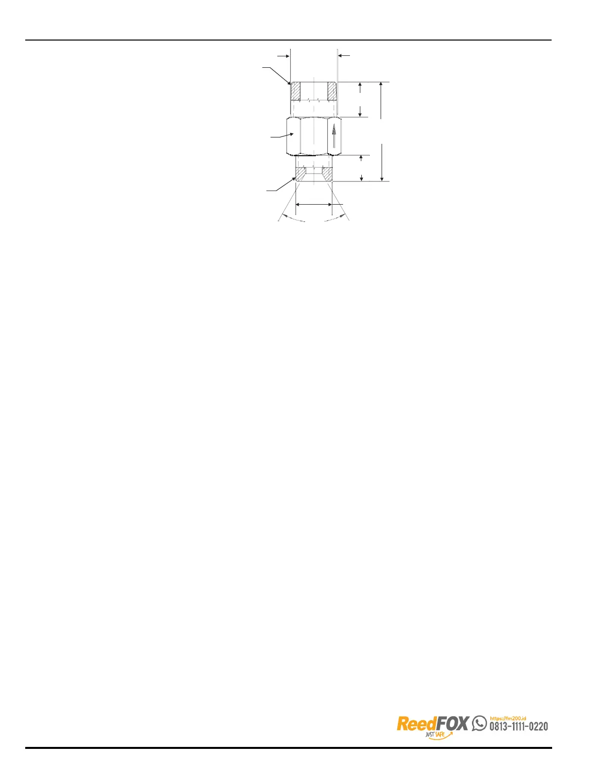
3/4" NPT
0.79
2.24
1.06
HEX
0.59
1/2" BSP
60°
CONNECTION FOR
DISCHARGE HOSE
CONNECTION
FOR MANIFOLD
Figure 6-8. Check Valve, P/N 38-509833-001
6-6 SELECTOR VALVE SYSTEMS
Selector valves are used in multiple hazard systems where Argonite may be supplied to different
hazards from the same cylinder bank. Refer to Figures 6-9, 6-10 and 4-2 for layouts of typical
selector valve arrangement.
Systems that utilize differing numbers of cylinders for each hazard MUST use a pilot line non-
return (check) valve (P/N 38-509832-001). This valve allows for a portion of the pilot line to be
used for system activation, as needed. Separate pilot cylinders must be used for each hazard.
For example, in Figure 4-2 when the Zone 1 pilot cylinder is activated, only 4 cylinders will
discharge into the manifold. When the Zone 2 pilot cylinder is activated, all nine cylinders will
discharge. The pilot line non-return valve (Figure 6-10) allows for the proper amount of Argonite
to be discharged into each hazard.
Using the standard primary completer kit assembly(s), the cylinders to be released are discharged
into the discharge manifold(s). At the end of the discharge manifold, customer supplied fittings
and/or a selector manifold is used to contain the Argonite pressure until the proper selector
valve is operated to release Argonite into the hazard area. The selector valves operate
pneumatically or manually.
The pressure required to operate the selector valves is taken from the discharge manifold via a
pressure regulator assembly (P/N 38-509803-001). One common regulator is used to reduce
the operating pressure to 120 PSI (8.3 bar) for selector valve actuation.
Each selector valve is equipped with its own actuator and is supplied with a 24 Vdc 3-way
solenoid. When actuated, the solenoid will route pressure to the actuator to open the selector
valve. Once opened, the selector valve will remain open until manually closed.
Restrictors for each hazard area are to be installed downstream of their respective selector valves.
Note: All discharge piping upstream of the restrictors, including the selector valve manifold,
must be Schedule 160 or stronger.