7-8 September 2004
Argonite
®
Engineered Fire Suppression System
38-KFSARG-000
7-10 DESIGN CONSIDERATIONS
7-10.1 Electrical Clearance
All system components shall be located so as to maintain minimum clearances from
live parts, as shown in Table 7-5. As used in this manual, clearance shall be the air
distance between equipment, including piping and nozzles, and unenclosed or
uninsulated live electrical components at other than ground potential.
The clearances in Table 7-5 are for altitudes of 3,300 feet (1,000 m) or less. At
altitudes in excess of 3,300 feet (1,000 m) the clearance shall be increased at the
rate of 1 percent for each 330 ft. (100 m) increase in altitude above 3,300 feet
(1,000 m).
Where the design BIL is not available and where nominal voltage is used for the
design criteria, the highest minimum clearance listed for this group shall be used.
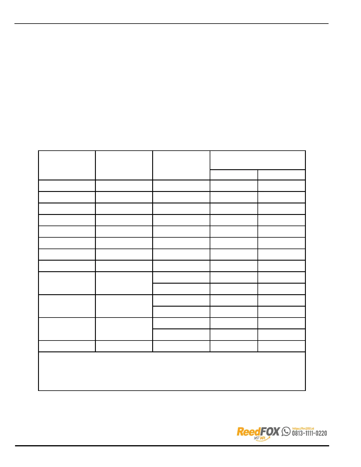
Table 7-5. Minimum Electrical Clearance
Nominal System
Voltage
(kV)
Maximum System
Voltage
(kV)
Design BIL(2) (kV)
Minimum Clearance
in. mm
13.8 14.5 110 7 178
23.0 24.3 150 10 254
34.5 36.5 200 13 330
46.0 48.3 250 17 432
69.0 72.5 350 25 635
115.0 121.0 550 42 1067
138.0 145.0 650 50 1270
161.0 169.0 750 58 1473
230.0 242.0
900 76 1930
1050 84 2134
345.0 362.0
1050 84 2134
1300 104 2642
500.0 550.0
1500 124 3150
1800 144 3658
765.0 800.0 2050 167 4242
Note:
1.
For
voltages up to 161 kV, the clearances are taken from NFPA 70, National Electrical Code. For voltages 230 kV
and above, the clearances are taken from Table 124 of ANSI C2, National Electrical Safety Code.
2.
B
IL values are expressed as kilovolts (kV), the number being the crest value of the full wave impulse test that the
electrical equipment is designed to withstand. For BIL values that are not listed in this table, clearances may be found
by interpolation.