6-12 July 2004
Argonite
®
Engineered Fire Suppression System
38-KFSARG-000
6.6.3 Isolation (Lockout) Valve Assemblies
Isolation (lockout) valves may be installed for maintenance/service reasons; for multi-
hazard systems they are typically installed upstream of the selector valve as illustrated
in Figure 4-2. For single hazard systems, the isolation valves shall be located upstream
of the restrictor. These devices MUST be locked in the OPEN position whenever the
Argonite System is in operational/standby condition. When the discharge piping is being
serviced, these valves MUST be locked in the CLOSED position.
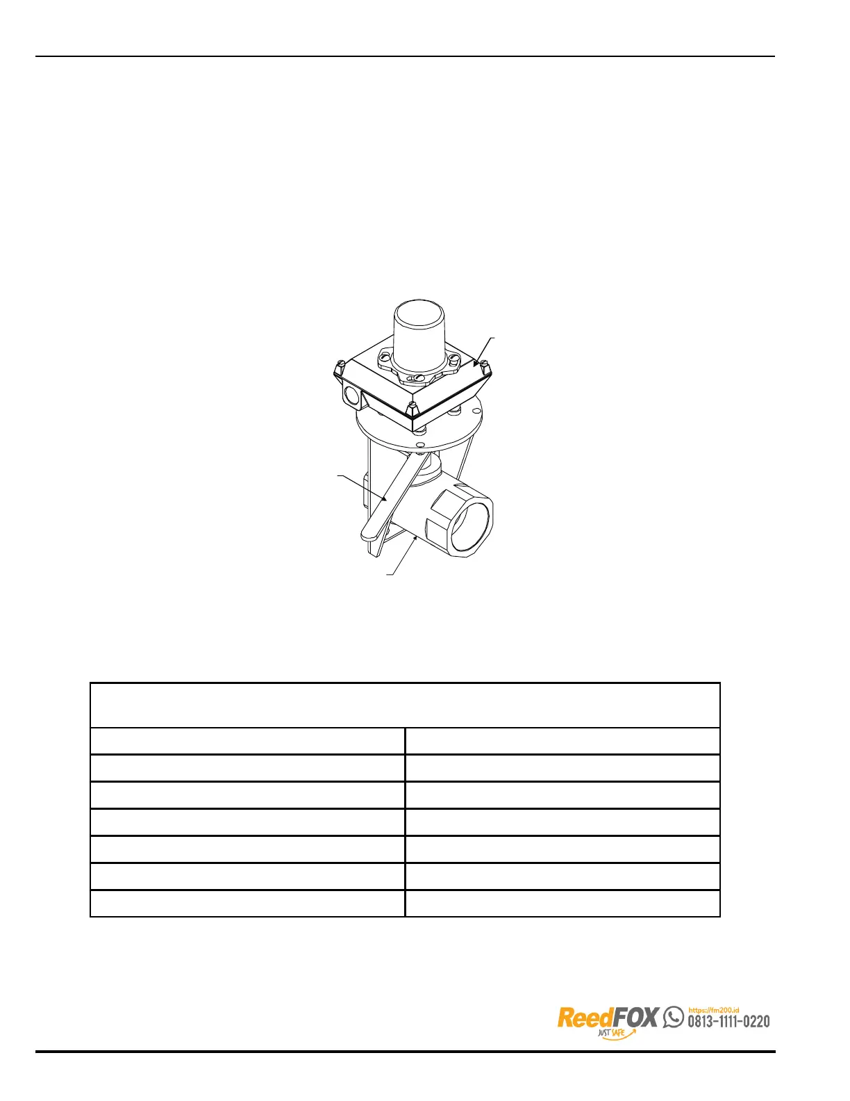
Isolation valve assemblies include a high visibility indicator and weatherproof limit switch.
The limit switch shall initiate a Trouble signal at the control panel when the ball valve
is in the closed position. All ball valves have a working pressure of 2900 PSI (200 bar).
When using isolation valves, a pressure relief valve should also be installed wherever
pressure could be trapped in closed sections of pipe.
LIMIT SWITCH
LOCKING HANDLE
HIGH PRESSURE
BALL VALVE
Figure 6-15. Isolation (Lockout) Valve, Typical
Table 6-8. Isolation (Lockout) Valve Assemblies
NEMA 4 and 4X
with Limit Switch, 2-SPDT
Part Number Size
38-509835-001 1/2 in.
38-509835-002 3/4 in.
38-509835-003 1 in.
38-509835-004 1¼ in.
38-509835-005 1½ in.
38-509835-006 2 in.