Chapter 8 Control Performance
8.1 Driver Performance Tuning
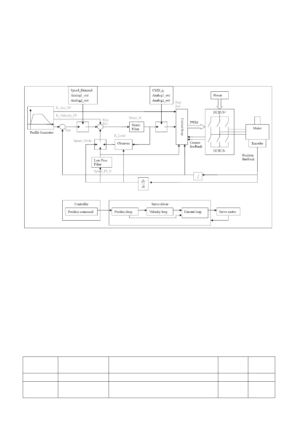
Fig. 8-1 Schematic diagram for control loop adjustment
As shown in Fig. 8-1, a typical servo system contains three control loops, namely, a position loop, a
velocity loop, and a current loop.
Current loops are related to motor parameters (optimal parameters of the selected motor are default for
the driver and no adjusting is required).
Parameters for velocity loops and position loops should be adjusted properly according to loading
conditions.
During adjustment of the control loop, ensure that the bandwidth of the velocity loop is at least twice of
that of the position loop; otherwise oscillation may occur.
8.1.1 Manual Adjustment
1. Parameters for velocity loop
Table 8-1 Parameters for velocity loop
Sets the response speed of a velocity loop
Adjusts speed control so that the time of
minor errors is compensated