Mathematical equation for dead zone processing:
externaldead
externaldead
deadexternalernal
deadexternaldeadernal
UU
UU
UUU
UUUU
int
int
0
Mathematical equation for integrated processing (offset and dead
zone)
shiftexternaldead
shiftexternald ead
deadshiftexternalernal
deadshiftexternaldeadernal
UUU
UUU
UUUU
UUUUU
int
int
0
Table 7-10 Analog signal variables
Internal data corresponding
to the external voltage
-10 V – 10 V corresponds to
-2048 – 2047 when no offset or
dead zone voltage exists
The obtained analog signal
obtains
after passing through a first-order low-pass filter, and is
applied by the internal programs again.
In the analog – speed mode, if the analog signal
that passes through the filter is multiplied by a factor,
this signal will be regarded as the internal target speed
.
Mathematical formula:
20472048*
filterfilterdemand
UUFactorV
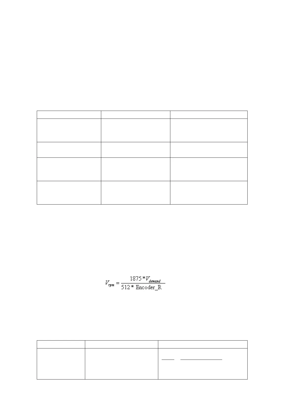
Formula for
conversion:
Note: The resolution unit of an encoder is inc/r.
7.2.4 Calculation Procedure for Analog – speed Mode
Table 7-11 Calculation procedure for analog – speed mode
according
to the offset voltage and dead
zone voltage that require
2047
10 10
filter
shift dead
U
v v U U