Chapter 6 Operation on Input/Output Ports
KINCO CD servo driver has 7 digital input ports (a digital input port can receive high-level or low-level
signals, depending on whether high-level or low-level signals are chosen at the COM terminal) and 5 digital
output ports,OUT1-OUT4 ports can drive 100 mA load, and OUT5 port can drive 800 mA load, and can
directly drive the internal contracting brake device(CD2 driver doesn’t have OUT5.There are terminals BR+、
BR-、24VB、GND in X2 port which are used for motor brake.It can drive 500mA load). You can freely configure
all functions on digital input/output ports according to application requirements.
6.1 Digital Input Signals
6.1.1 Polarity Control on Digital Input Signals
Table 6-1: Simplified IO polarity setting variables
Table 6-2 Polarity setting methods for digital input signals
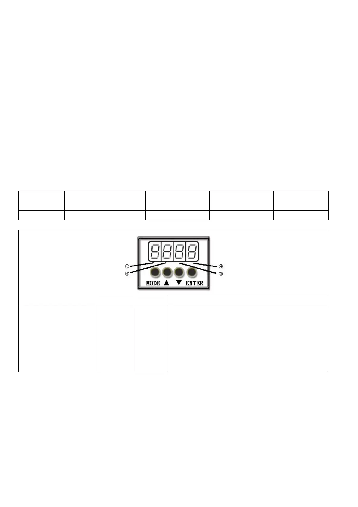
Input/output port
selection
0: Output port
1: Input port
Channel
selection
Input: 1-7
Output:
1-5
0: The input port is valid when no current passes the
port, and the output port is valid when the switch tube
is open..
1: The input port is valid when the current passes the
port, and the output port is valid when the switch tube
is closed.
Other: Check the current status