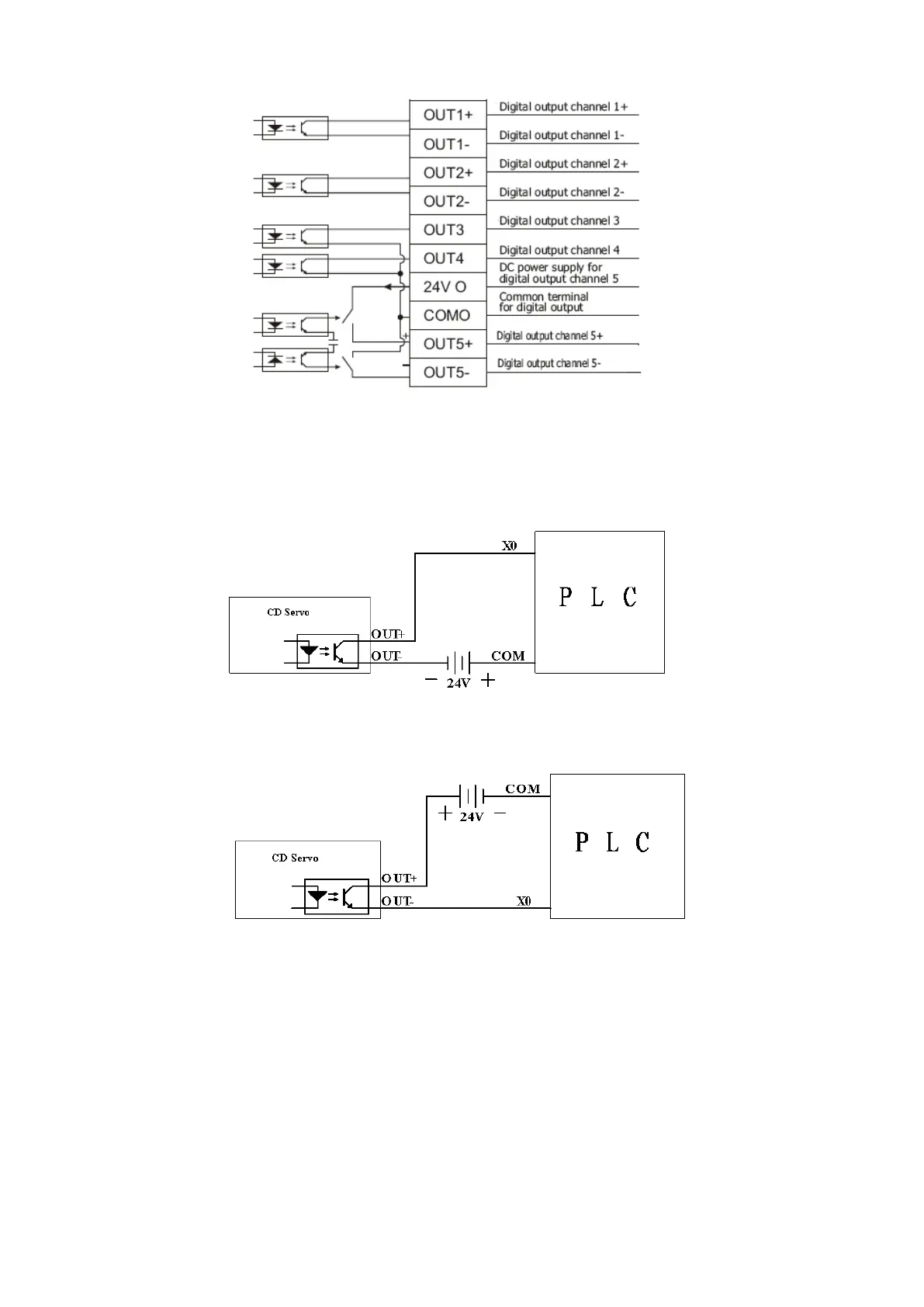
Fig. 6-4 Internal circuit diagram of digital output ports
Note: To apply the OUT3 or OUT4 port, the COMO port must be connected. To apply the OUT5 port, both the
24VO and COMO ports must connect to the external input power.(CD2 driver don’t have OUT5,it uses BR+、
BR-、24VB、GNDB for motor brake)
2. NPN wiring (to controllers that support valid low level input)
Fig. 6-5 NPN wiring diagram (to controllers that support valid low level input)
3. PNP wiring (to controllers that support valid low level input)
Fig. 6-6 PNP wiring diagram (to controllers that support valid low level input)
4. To connect a relay to the digital output port, do remember to connect a diode in inverse parallel, as
shown in Fig. 6-7.