35
Venting Routes And Components
Since it is important that the vent system maintain its
balance between the combustion air intake and the
flue gas exhaust, certain limitations as to vent
configurations apply and must be strictly adhered to.
The table showing the relationship between vertical
and horizontal side wall venting will help to
determine the various vent lengths.
For horizontal vent runs using 90° bends with
vertical runs from Fireplace, 1/4" rise per ft. using
venting table. See Fig. 3.
2 additional 90° bends or equals are allowed. The
horizontal run must be reduced by 36" per each 90°
bend, or 18" per each 45° bend.
Maximum vertical run is 40 ft. (12.2 meters)
Locate the fireplace in such a way to minimize the off
sets and/or horizontal runs that are required.
Insulation sleeve over 7" pipe is required for low
profile enclosures with Combustible top 2.0"
from top of flue pipe, to 13.0" from top of flue
pipe. For Combustible top 14.0"+ above flue pipe
require no insulation sleeve in enclosure.
How To Use The Vent Table
1. Determine the height of the system and the
number of bends required.
2. Having determined the vertical distance,
deter mine the maximum horizontal section allowed.
3. Vent table has been established for 90°
horizontal/vertical runs. With use of flex pipe
distance not having 90° bends will not fall into vent
table standards. See Fig. B.
Venting Table From Bottom Of Fireplace
For venting to a maximum of 40 ft. (12.2 meters)
Total Vertical Max. Total Horizontal
Feet Meters Feet Meters
4 1.2 8 2.4
5 1.5 15 4.5
6 1.8 15 4.6
7 2.1 20 6.1
8 2.4
20 6.1
9 2.7
20 6.1
10 3.0
20 6.1
11 3.4
20 6.1
12 3.7
20 6.1
13 4.0
20 6.1
14 4.3
20 6.1
15 4.6
20 6.1
16 4.9
20 6.1
17 5.2
20 6.1
18 5.5
20 6.1
19 5.8
20 6.1
20 6.1
20 6.1
25 7.5 15 4.6
30 9.1 10 3.0
40 12.2 0 0
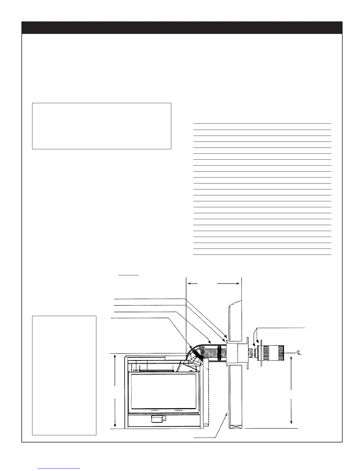
FIGURE 1
MAX. HORIZONTAL RUN
WITH MIN. VERTICAL
RUN 1/4" RAISE PER FT.
Up To 34.0"
MAX.
34.0"
35.0"
36.0"
1/2"
REQUIRES ZDVHSK
STARTER KIT
CAULK (BOTH SIDES)
SILICONE
SCREW
MINIMUM FROM
BASE TO CENTER
OF TERMINATION.
WALL SLEEVE
INSULATION SLEEVE
SPRING SPACER
It is recommended for
Propane Horizontal
Installations that the
venting should be a
minimum of one foot
vertical off the flue
before the elbow on
any horizontal runs of
one foot or greater.
This allows for cleaner
combustion and greatly
reduces carboning and
cleaning of glass.
(Does not apply to
Back Flue Models).
For horizontal vent runs with minimum vertical
venting of 4 feet:
12" to 34" horizontal runs require 1/4" rise per foot.
See Figure 1.
34" to 240" horizontal runs require 2 1/2" rise per foot.
See Figure 2.
Horizontal Venting Routes
 Loading...