DP580 Service Manual
4.3.Rx Circuit
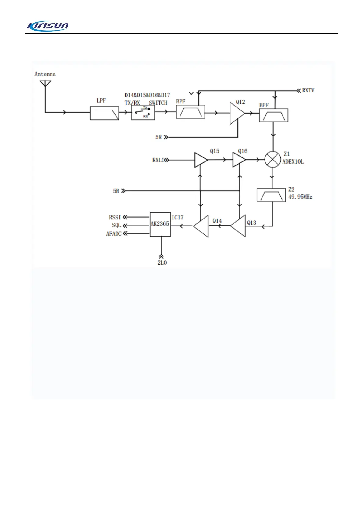
The receiving circuit mainly consists of an RF circuit, an MF circuit and MF signal processing, which are
described as below.
RF Circuit
Signals from the antenna are filtered through a low-pass filter circuit, transmitted by the RX/TX switch (D14.
D15, D16 and D17) to a tunable band-pass filter for filtering, amplified by the low-noise amplifier Q12,
filtered by another tunable band-pass filter, and then mixed with the first local oscillator signals in the mixer
Z1 to get the first MF signals at a frequency of 49.95MHz.
MF Circuit and MF Signal Processing
The first MF signals are filtered by the crystal filter Z2, amplified by the amplifiers Q13 and Q14, mixed
again and processed by the MF decoding chip IC17 to get noise signals, signal strength and audio signals,
which are processed by the DSP in the master chip LT1901.
8

 Loading...


