DP580 Service Manual
and the TX VCO for modulation.
4.6.Other Circuits
If required, such functions as Bluetooth, GPS and Man Down can be provided by adding corresponding
circuits.
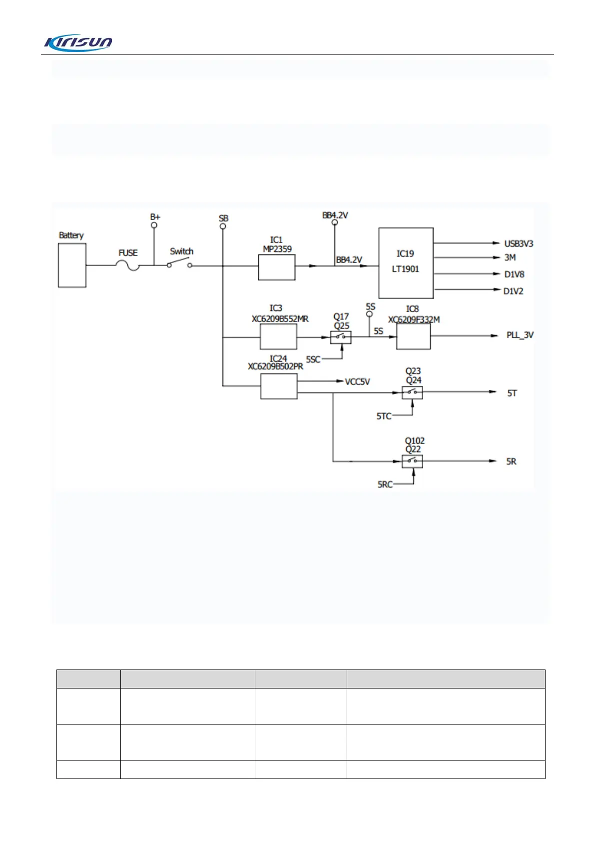
4.7.Power Supply
The radio is powered by a 7.4V lithium battery. The RF amplifier and the audio amplifier are powered by the
B+ connected to a fuse. The voltage SB through a mechanical switch is converted by the DC-DC chip
MP2359 into 3.6V to power up the master chip LT1901 and the PMU in the Bluetooth chip. The PMU of the
LT1901 outputs 3M, AVDD_2V8, USB3.3V, D1V8 and D1V2A to power up other parts.
The voltage SB passes the LDO chip IC3 to output 5.5V to power up the phase-locked loop, and passes the
LDO chip IC24 to output 5V, which goes respectively through two switches consisting of triodes to output
5T to power up the transmitting circuit and to output 5R to power up the receiving circuit.
4.8.Port Definition for Master Chip LT1901
A11 GPIO_D46 5SC
Power switch of phase-locked loop (on
at high level)
B13 GPIO_D47 5RC
Receiving power switch (on at high
Transmitting power switch (on at high
10