DP580 Service Manual
4.4.Audio Amplification Circuit
The master chip LT1901 processes signals to get differential audio signals, which are amplified by an audio
power amplifier and output via the speaker or the headset.
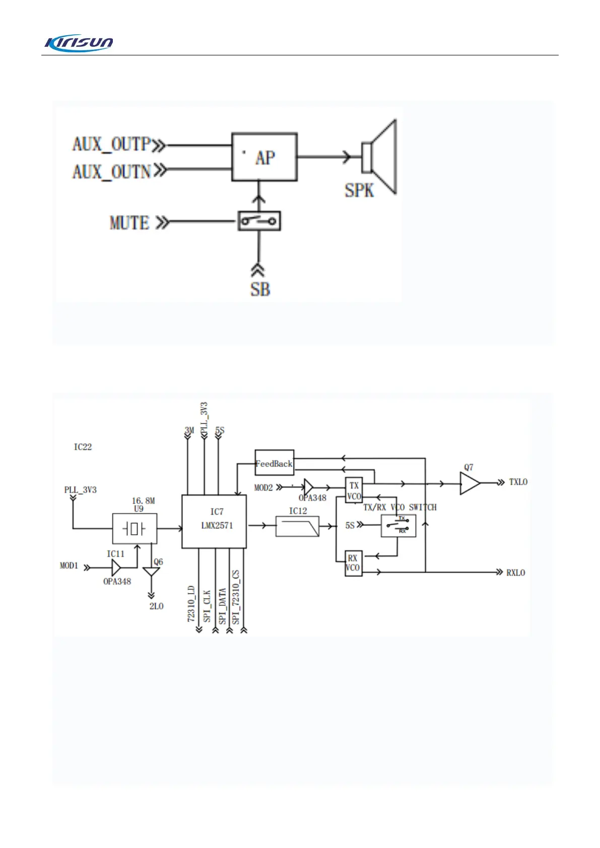
4.5.Frequency Synthesis Circuit
The frequency synthesis circuit consists of the phase-locked loop (PLL) chip LMX2571, a loop filter (LPF), a
voltage-controlled oscillator (VCO) and a feedback network.
To the LMX2571, a 16.8MHz work clock is provided by the active resonator U9 and configuration data is
provided by the master chip LT1901. The LPF consists of a 4-stage resistor–capacitor (RC) filter circuit.
The TX VCO and the RX VCO respectively includes the varicap 1SV305, an inductor, a capacitor and the
transistor 2SC3356. The feedback network consists of an inductor and a capacitor. The TXLO signals and
RXLO signals, which are generated through frequency synthesis, are sent to the transmitting circuit and the
receiving circuit respectively. Modulated signals MODE1 and MODE2 are respectively transmitted to the U9
9

 Loading...


