DP990/DP995service manual
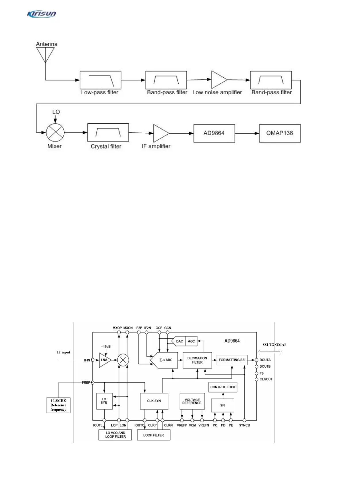
3.3.Rx Circuit
The Rx circuit is mainly composed of RF band-pass filters, a low-noise amplifier, a mixer, an IF filter, an IF
amplifier and an IF processor.
Front end of Rx circuit
High-frequency signals from a low-pass filter pass an electrically tunable bandpass filter 1 the level TV1 controls
for filtering out-of-band interference signals, and effective bandpass signals enter a low-noise amplifier (Q1205) for
amplification.
The amplified signals pass a bandpass filter 2 controlled by the level TV1 to filter out-of-band interference signals
caused by amplification, and effective signals enter a mixer (IC5).
At this moment, the first local oscillator signals the VCO generates pass the low-pass filter and enter the mixer for
difference frequency mixing
with the effective signlas to generate the first IF singals (73.35MHz for UHF and 51.65MHz for VHF).
The signals pass an LC frequency-selective network to enhance the surpression of other carrier except the first IF
signals to increase the isolation between the mixer and the IF filter, and then pass the crystal filer (F1200) for
filtering. Then, the siganls are sent to a two-stage series IF amplifier circuit (Q1203 + Q1202) for amplification. The
amplified signals enter an IF subsystem AD9864 (U1201) for digitization.
Back end of Rx circuit (AD9864 IF Processor)
 Loading...