viii
Series 5000 V2 Sonar System Operations and Maintenance Manual P/N 11214512, Rev. 04
List of Figures
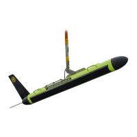
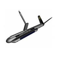
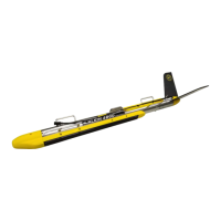
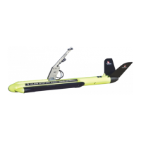
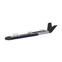
Figure 1-1: Series 5000 Towfish . . . . . . . . . . . . . . . . . . . . . . . . . . . . . . . . . . . . . . . . . . . 1-3
Figure 1-2: Series 5000 V2 Sonar System Topside System Main Components . . . . . . . . 1-4
Figure 3-1: TPU Back Panel . . . . . . . . . . . . . . . . . . . . . . . . . . . . . . . . . . . . . . . . . . . . . . 3-7
Figure 3-2: SonarPro Workstation Back Panel . . . . . . . . . . . . . . . . . . . . . . . . . . . . . . . . 3-9
Figure 3-3: TPU Front Panel . . . . . . . . . . . . . . . . . . . . . . . . . . . . . . . . . . . . . . . . . . . . 3-12
Figure 3-4: SonarPro Workstation Front Panel . . . . . . . . . . . . . . . . . . . . . . . . . . . . . . 3-14
Figure 4-1: Towfish Tail with Rear Center Pin in Place . . . . . . . . . . . . . . . . . . . . . . . . . 4-3
Figure 4-2: Tail Cone being Aligned and Attached to Towfish . . . . . . . . . . . . . . . . . . . . 4-4
Figure 4-3: Tail Cone Being Tightened with Hex Key . . . . . . . . . . . . . . . . . . . . . . . . . . 4-4
Figure 4-4: Crossbar Used to Secure Tail Cone Parts . . . . . . . . . . . . . . . . . . . . . . . . . . 4-5
Figure 4-5: Tail Cone Being Tightened With Screwdriver and Key . . . . . . . . . . . . . . . . 4-5
Figure 4-6: Tail Fins being Inserted into Tail Cone . . . . . . . . . . . . . . . . . . . . . . . . . . . . 4-6
Figure 4-7: Tail Fins being Secured to Tail Cone . . . . . . . . . . . . . . . . . . . . . . . . . . . . . . 4-6
Figure 4-8: Push/Pull Assembly . . . . . . . . . . . . . . . . . . . . . . . . . . . . . . . . . . . . . . . . . . . 4-7
Figure 4-9: Jacking Screw . . . . . . . . . . . . . . . . . . . . . . . . . . . . . . . . . . . . . . . . . . . . . . . . 4-7
Figure 4-10: Electronics Housing End Cap Bulkhead Connectors . . . . . . . . . . . . . . . . . . 4-8
Figure 4-11: Altimeter Cable Identified with Colored Shrink Tubing . . . . . . . . . . . . . . . . 4-8
Figure 4-12: Towfish Electronics Ready for Servicing . . . . . . . . . . . . . . . . . . . . . . . . . . . 4-9
Figure 4-13: Multiplexer Board Waveforms . . . . . . . . . . . . . . . . . . . . . . . . . . . . . . . . . . 4-11
Figure 4-14: Sample Transmit Waveform . . . . . . . . . . . . . . . . . . . . . . . . . . . . . . . . . . . . 4-11
Figure 4-15: The Sensor Interface Board . . . . . . . . . . . . . . . . . . . . . . . . . . . . . . . . . . . . 4-12
Figure 5-1: Towfish Block Diagram—12 Sidescan Channels and 3 Bathymetery
Channels . . . . . . . . . . . . . . . . . . . . . . . . . . . . . . . . . . . . . . . . . . . . . . . . . . . . 5-2
Figure 5-2: The Series 5000 V2 Sonar System TPU Electronics Chassis . . . . . . . . . . . . 5-3
Figure 5-3: The Series 5000 V2 Sonar System TPU Electronics Block Diagram . . . . . . 5-6
Figure 5-4: The Series 5000 V2 Sonar System TPU Electronics Chassis . . . . . . . . . . . . 5-7
Figure A-1: Cable Length vs. Towfish Depth Graph 1 . . . . . . . . . . . . . . . . . . . . . . . . . . A-3