D-2 APPENDIX D Different Tow Cable Lengths and the Startup.ini File
Series 5000 V2 Sonar System Operations and Maintenance Manual P/N 11214512, Rev. 04
For example, when testing a 1000-meter cable, from SonarPro the following
command set yielded error-free operation: $MG2 and $ML7. Therefore the
Startup.ini file would be adjusted to contain the following:
set PREEMPHISIS 7
set LBOGAIN 2
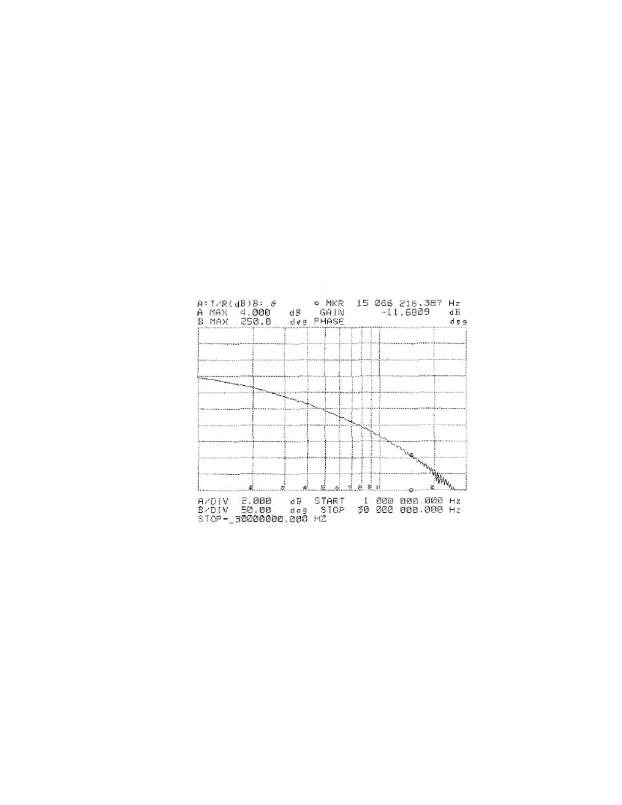
D.1 Measuring Cable Insertion Loss
To get an accurate assessment of your tow cable assembly, we suggest that you use
a Hewlett Packard 4194A Impedance/Gain-Phase Analyzer or similar.
A sample plot is shown in Figure D-1.
If you do not have access to a Hewlett Packard 4194A Impedance/Gain-Phase
Analyzer, you can get a close reading by using a function generator, a 50-ohm
terminator and an oscilloscope as shown in Figure D-2.
With the function generator and the oscilloscope connected to the cable, monitor
input on the oscilloscope and input a 1 volt peak (2 volt peak-to-peak) sine wave of
the specific frequency of interest. Measure the peak output at the other end of the
cable on the scope through the 50-ohm termination.
Figure D-1: Sample Plot of Tow Cable Characteristics
 Loading...