14
Installation of the new torque arm requires the following:
2, grade5, ½”-13 UNC bolts, 2” long. (the 1-1/2” long bolts that come stock with the pump and speed
increaser are not long enough once the torque arm is installed.)
2, ½” flat washers
2, ½” lock washers
2 drops of Teflon based thread sealant (DO NOT USE THREAD TAPE!)
Start by turning off the oil supply from the
reservoir. Also, since there is no way to stop the
oil from coming out of the gearbox case drain line,
remove the case drain hose and position the end
of the hose so that it is at a higher elevation than
the fluid level in the tank.
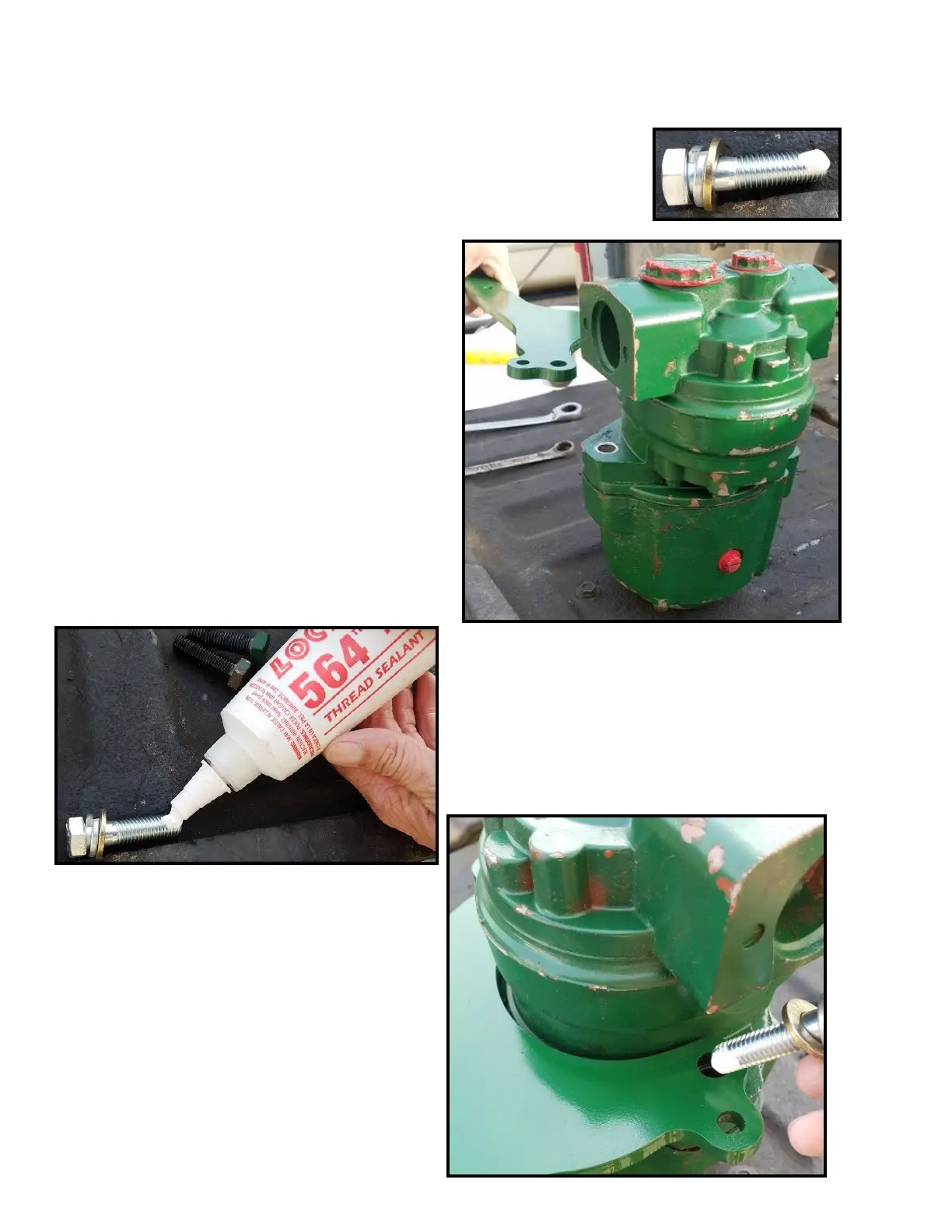
Next, use a ¾” wrench to remove the two bolts
that hold the gear pump to the speed increaser,
But use care not to separate the pump from the
speed increaser as there is a large o-ring between
the two that could be damaged if not properly rein-
stalled.
With the pump and speed increaser still together,
hold the speed increaser and the plate between
the pump and speed increaser while rotating the
pump 180°. The holes should line back up and
the longer side of the pump should be aligned with
the case drain hole on the speed increaser.
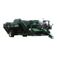
Install the lock washer, then the flat
washer onto the bolt, and then place a small
amount of the Teflon based thread sealant on
the 2” long bolts as shown.
Align the torque arm so that the offset on
the torque arm and the big hose is on the
right hand side of the pump when looking at
the rear of the pump. Insert, hand start the
two, 2” bolts and tighten with a ¾” wrench.
Index the 90° hydraulic adapter so that
when the hose is installed, it will just pass
by the pump on the left hand side (This is
so the hose cannot become loose over
time.)
Re-install the case drain hose to the
speed increaser.
 Loading...