3 Working with the stud welding equipment
3.1 Requirements before start-up
1. The power connection must be earthed according to regulations.
2. The housing of the power source must not have any electrical contact with the workpiece. Make sure
that the insulating supporting legs are in perfect condition!
3. Make sure that the power source is standing firm on vibration-free, dry ground.
4. Ensure adequate cooling! The circulation of air must not be restricted in any way.
5. Operating the equipment in a fire or explosion danger area is prohibited. In case of doubt obtain a
release for the welding operation from the security officer in charge.
6. Keep a safe distance from any objects which may be affected by strong magnetic fields, such as EDP instal-
lations!. Persons wearing heart pace-makers must keep away from the welding cables!
3.2 Start-up of the ESP 1 S Welding Gun
1. Attention: Setting of the gun may only be carried out while the power source is switched off!
2. Attach the leg ring with its three legs or the support tube to the gun and tighten the Allen screws around
the circumference. When using a support tube, make sure that the protective rubber cap is not wedged in;
oth-erwise it may obstruct the movements of the piston. For studs above 40 mm length, a height
adjustment ring, part No. 351-0053-000, must be inserted between the body of the gun and the leg ring
and the stop screw must be reversed if necessary (half dog point outwards). For studs exceeding a length
of 55 mm spacer bolts (see chapter 12.1) need to be mounted between feet and base ring.
Alternatively, for long studs you may use a gun support acc. to chapter 12.1.1. In this case the stud
flange should protrude the end of the supporting tube by 1 to 2 mm. The suitable setting shall be
determined by trial welds.
For M 10 studs please note: mount spacer bolts (see chapter 12.1) between the legs and the base
ring, since the stepped chuck (part No. 351-7010-000) allows only a reduced insertion depth. The
minimum length of the stud is 20 mm, for which spacer bolts with a length of 10 mm are required. Longer
studs re-quire the use of more or longer distance bolts.
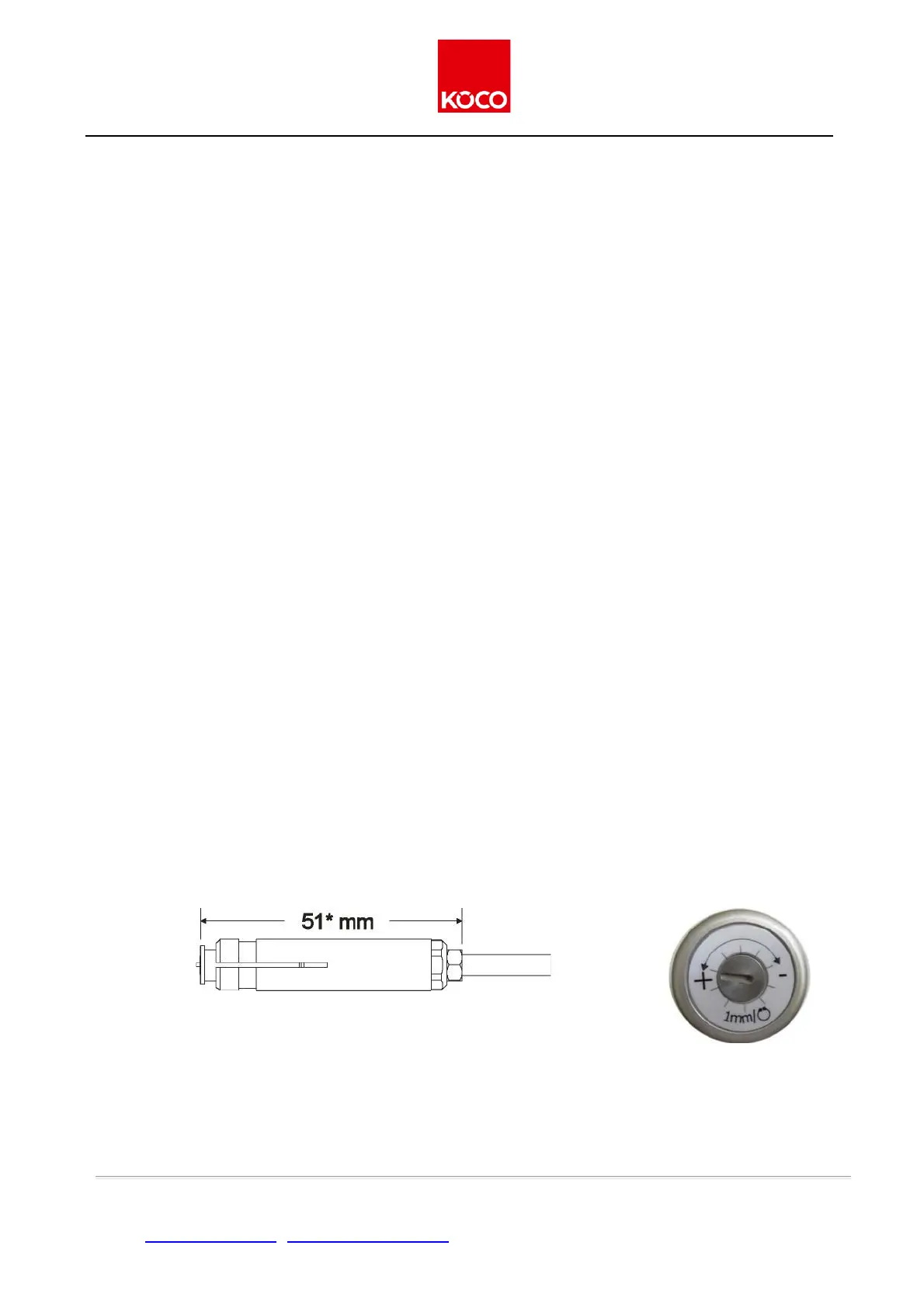
3. Push a stud of the required size into the chuck. Then adjust the stop screw to provide a gap of 51 mm
be-tween the end of the stud (not including the ignition tip) and the upper edge of the counter-nut (see
fig.2). This extends the chuck’s service life by protecting it against splashes. Now tighten the counter-nut
to lock the stop screw into position.
Fig. 2: Set-up of the chuck for gun ESP 1 S for studs with
max. length 40 mm
* 67 mm for studs with length exceeding 40 mm
* 57 mm for studs M 10
Figure 3: setting disk of
the pistol ESP 1 S
4. Push the chuck into the gun to the stop, and then lock it into position with a 17 mm gauge spanner.
By turning the setting screw clockwise (see Figure 3) the gap is in each case narrowed by one millimeter for
Issue 4/2019 ver. 2.0 page 13 of 42
Köster & Co. GmbH • D-58256 Ennepetal • Spreeler Weg 32 • Tel. +49 2333 8306-0 • Fax +49 2333 8306-38
Internet: http://www.koeco.net • E-Mail: koeco@koeco.net