1. Make sure that the mains switch is in the „0“ position. Then plug in the mains plug.
2. Connect the ground cables to the ground sockets of the power source and the workpiece. The connection
points on the workpiece must be bright metal. Preferably, the earthing clamps should be mounted on oppo-
site sides of the workpiece. Lock the ground cable plugs by turning them clockwise to the stop.
3. Connect the welding and control cables of the gun to the correct sockets of the power source. Lock
the welding cable plug by turning it clockwise to the stop.
Note: as a rule, the stud is connected to the minus pole and the workpiece to the plus pole. In certain
cases, especially when welding non-ferrous metals, reversed polarity may improve the welding results. The
power source is capable of welding with either polarity.
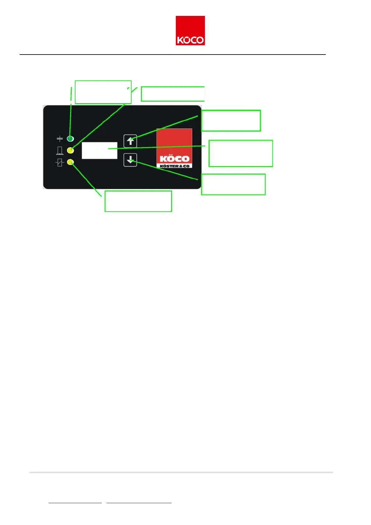
4. Turn on the mains switch to switch on the power source. The red pilot lamp will light up, and charging of
the appliance to the set charging voltage will begin.
5. You can change the charging voltage by pressing the "UP" und "DOWN" buttons. Choose the voltage
charging in accordance with the recommendations in 3.5 or according to your experience.
6. As soon as the charging voltage has been reached, the green pilot lamp (READY) will light up to signal that
the power source is ready for welding.
3.6 Setting values for stud welding with tip ignition
Explanations:
On the pistol ESP 1 K the spring force is increased by approx. 14 N per turn (Figure 5) by turning the setting
screw clockwise. Start with the minimum value (turn the setting screw anticlockwise till it reaches the stop) and
set the required spring force from this starting point.
Set the required charging voltage at the power source. Example: a recommended value of "95 / +3" means: 95
V charging voltage and 3 clockwise turns from the minimum value.
On the pistol ESP 1 S the gap is reduced by 1 mm per turn respectively by turning the setting screw clockwise.
Start with the minimum value (turn the setting screw anticlockwise till it reaches the stop) and set the required
gap from this starting point.
Set the required charging voltage at the power source. Example: a recommended value of "100 / -4" means: 95
V charging voltage and 4 clockwise turns from the minimum value.