each turn of the screw.
A large gap shortens the welding time, a small gap lengthens the welding time.
Now place the gun firmly on the workpiece so that all support legs are resting on the surface. The piston
should now be pushed back by app. 1.5 mm (“protrusion”).
3.3 Start-up of the ESP 10 K Welding Gun
1. Attention: Setting of the gun may only be carried out while the power source is switched off!
2. Attach the leg ring with its three legs or the support tube to the gun and tighten the Allen screws around the
circumference. When using a support tube, make sure that the protective rubber cap is not wedged in, oth-
erwise it may obstruct the movements of the piston. For studs above 40 mm length a height adjustment ring,
part No. 351-0053-000, must be inserted between the body of the gun and the leg ring and the stop screw
must be reversed if necessary (half dog point outwards). For studs exceeding a length of 55 mm spacer
bolts (see chapter 11.1) need to be mounted between feet and base ring.
Alternatively, for long studs you may use a gun support acc. to chapter 12.1.1. In this case the stud flange
should protrude the end of the supporting tube by 3 to 4 mm. The suitable setting shall be determined
by trial welds.
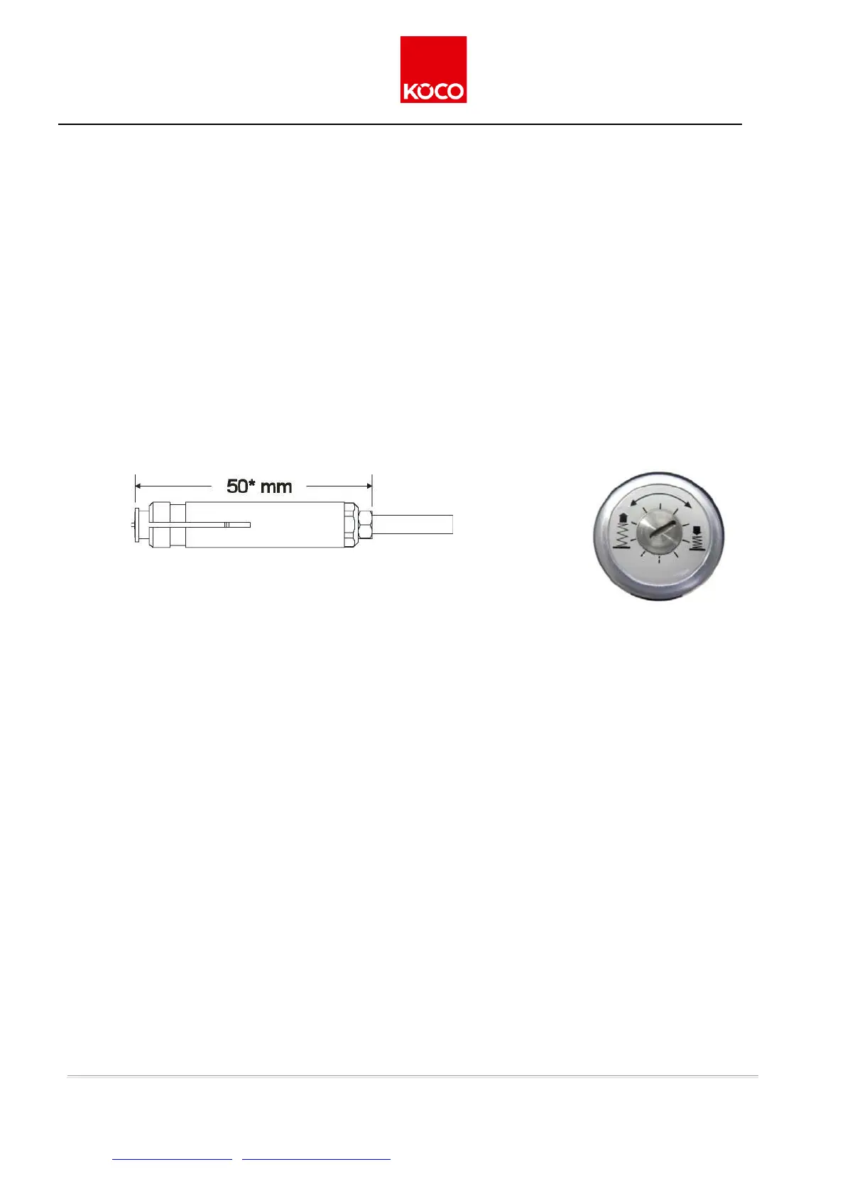
Fig. 4: Set-up of the chuck for gun ESP 1 K for studs with max.
length 40 mm
* 66 mm for studs with length exceeding 40 mm
* 57 mm for studs M 10
Figure 5: setting disk of
the pistol ESP 1 K
For M 10 studs please note: mount spacer bolts (see chapter 11.1) between the legs and the base
ring, since the stepped chuck (part No. 351-7010-000) allows only a reduced insertion depth. The
minimum length of the stud is 20 mm, for which spacer bolts with a length of 10 mm are required. Longer
studs re-quire the use of more or longer distance bolts.
3. Push a stud of the required size into the chuck. Then adjust the stop screw to provide a gap of 50 mm
be-tween the end of the stud (not including the ignition tip) and the upper edge of the counter-nut (see
fig.4). This will protect the chuck against welding splashes, thus extending its service life. Tighten
Tighten the counter-nut to lock the stop screw into position.
4. Push the stud back into the gun to the stop, and then lock it into position with a 17 mm gauge spanner.
5. By turning the setting screw clockwise (see Figure 5) the spring force can be respectively increased by
approx. 14 N, beginning with a minimum value of approx. 50 N up to a maximum value of 130 N.
High spring tension shortens the welding time, low spring tension lengthens the welding time.
6. Press the pistol firmly onto the workpiece, so that all its legs are firmly seated. The piston should only be
compressed a few millimetres.
Issue 4/2019 ver. 2.0 page 14 of 42
Köster & Co. GmbH • D-58256 Ennepetal • Spreeler Weg 32 • Tel. +49 2333 8306-0 • Fax +49 2333 8306-38
Internet: http://www.koeco.net • E-Mail: koeco@koeco.net