TP-5648 8/93 Controller Troubleshooting 5-1
Section 5. Controller Troubleshooting
Sequence of Operation
The following text describes the controller sequence of
operation during starting, running, and stopping of the
generator set. Use this section as a starting point for
controller fault identification.
Starting
Preheating. Preheating of the glow plugs in the diesel
engineis initiatedby rockingthe start/stopswitch onthe
control panel to the STOP/PREHEAT position for the
time period specified in Section 2. This action energizes
the GP relay. As a result, normally open contacts of the
GP relay close to energize the glow plugs.
At the end of the specified time period, the start/stop
switch is released or switched out of the
STOP/PREHEAT position. Either of these actions
opens the ground path to the GP relay, de-energizing
the GP relay and the glow plugs.
Engine Startup. The engine is started after glow plug
preheating by rocking the start/stop switch on the
controlpaneltotheSTARTposition. At thispoint,theES
(EmergencyStop)switchonthecontrolpanelmustbein
its normal position and the 10 ampere fuse must be
good. If not, power to the starting circuits is interrupted
and none of the other actions described in this
paragraph occur.
Setting the Start/Stop switch to the START position
energizes the K2 relay (LED2 lights). As a result,
normally open contacts of K2 close to energize the K3
relay, the K25 relay, and the FP (Fuel Pump) motor.
Energizing the K3 relay (LED3 lights) causes a set of
normallyopencontacts tocloseandenergizerelayK20.
A set of normally open contacts of K20 then close to
energize the S solenoid (Starter Solenoid). As a result,
normally open contacts of the S relay close to energize
theM(starter)motorandthestartermotorgearengages
the ring gear on the engine flywheel to begin cranking
the engine. At the same time, the power supplied to
starter motor also energizes the pull-in coil of the FS
(Fuel Solenoid).
Energizing the K25 relay closes a set of normally open
contacts to energize the hold coil of the fuel solenoid to
complete the conditions necessary for engine startup.
Releasing the Start/Stop switch allows the switch to
return to its neutral position. If the switch is released
before the engine starts (the K1 relay is still
de-energized), the K2 relay de-energizes. The normally
open contacts of the K2 relay then open to interrupt
power to the engine startup circuits. As a result the K3
relay, the K25 relay, the K20 relay, the Fuel Pump, the
Fuel Solenoid, and the Starter Solenoid all de-energize
to cease startup of the engine.
12 VDC
GP
GLOW PLUGS
GP
M
FS
S
10 A.
K25
K25
FP
10 A.
ES
START
STOP/
PREHEAT
K1C
K1D
K1E
K2
K20
K3
K4
K2
K3
K20
S
B.C.
ALT
LED3
LED2
TO REMAINING
CIRCUITS
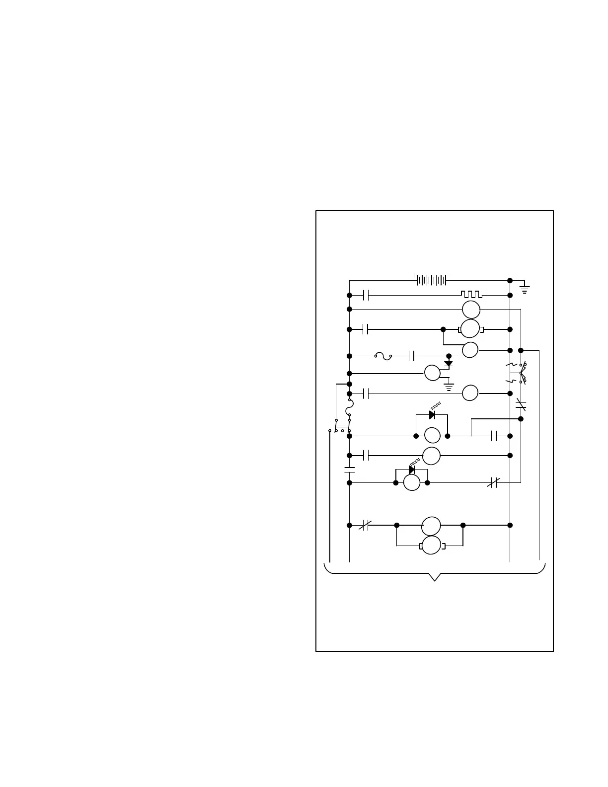
Figure 5-1. Sequence of Operation, Starting
 Loading...

