TP-5648 8/935-2 Controller Troubleshooting
Running
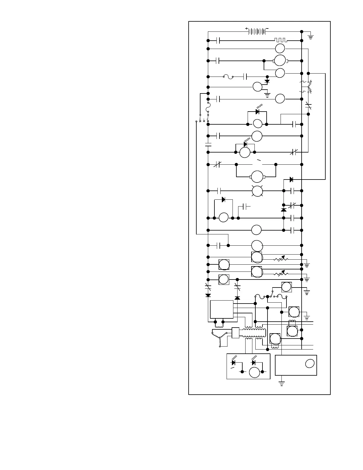
Duringenginestartup,flashingcurrent isprovidedtothe
generator exciter field through a normally open contact
of the K2 relay and normally closed contacts of the K1
relay. The resulting generator output from the B1/B2
stator winding, rectified and limited to a 12 VDC level,
energizes the K1 relay (LED1 lights). After a 5 to 10
second delay, the K5 relay is energized (LED5 lights).
Both relays remain energized during normal running.
Energizing the K1 relay opens the normally closed K1A
and K1B contacts that supply flashing current to the
generator exciter field. Field exciter current for
continued operation is then supplied by the voltage
regulator, operating from an input supplied by generator
stator winding 55/66.
Energizing the K1 relay opens the normally closed K1C
contactsbetweentheStart/StopswitchandtheK2relay
in the engine startup circuit.However, at the same time,
the normally open K1D contacts close to keep the K2
relay energized in order to maintainoperating power for
the other relays and the hourmeter, oil pressure gauge,
watertemperature gauge, and batteryvoltagegaugeon
the controller front panel as well as the overspeed
protection circuit board within the controller.
Energizing the K1 relay opens the normally closed K1E
contacts to de-energize the K3 relay. As a result, K20
and the S (Starter) solenoid de-energize to disengage
and de-energize the starter motor, even when the
Start/Stop switch is held in the Start position. The other
devices energized during engine starting, that is relay
K25, the fuel pump, and the fuel solenoid, remain
energized to keep the engine running and to supply
excitation to the B.C. Alt (battery charging alternator).
Finally,energizingtheK1relayclosesthenormallyopen
K1F contacts to supply a high to the F (Fault) light. The
fault light and the shutdown switches that activate it are
explainedintheSafetyShutdown paragraphonthenext
page.
F
K1F
FROM SAFETY
SHUTDOWN
SWITCHES
K5
K4A
LED4
K4
K2
SDR
K7
K7
K7
K6
OP
WT
HR
BV
K1BK1A V
1.5 A.1.5 A.
HZ
A2
A1
MAIN FIELD
L2
LO
LO
L1
SDR
OVERSPEED
PROTECTION
CIRCUIT BOARD
VOLTAGE
REGULATOR
LED1 LED5
K1 K5
12 VDC
GP
GLOW PLUGS
GP
M
FS
S
10 A.
K25
K25
FP
10 A.
ES
START
STOP/
PREHEAT
K1C
K1D
K1E
K2
K20
K3
K4B
K2
K3
K20
S
B.C.
ALT
LED3
LED2
Figure 5-2. Sequence of Operation, Running
 Loading...

