8-6 Disassembly/Reassembly TP-5648 8/93
23. Remove the eight screws securing the armature
drivediskstotherotorassemblyusinga9/16-inch
socket wrench and ratchet. See Figure 8-18.
Figure 8-18. Removing the Armature Drive Disks
Reassembly
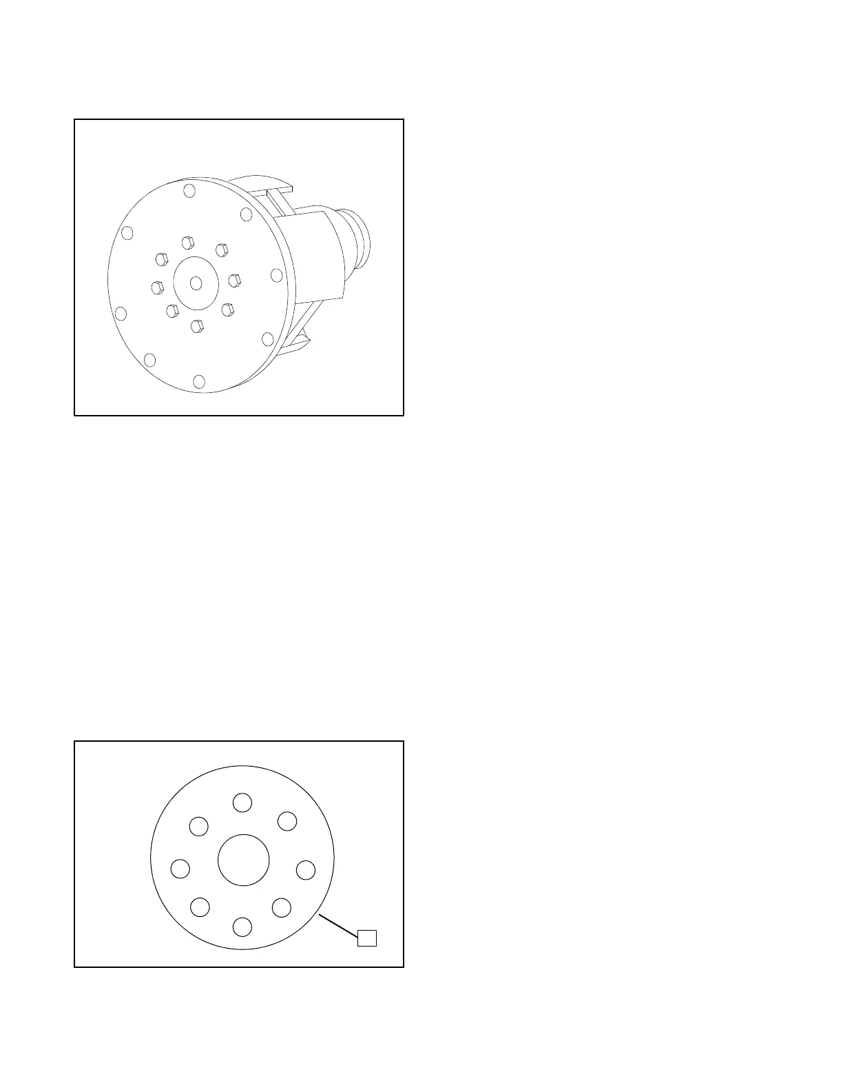
1. Secure the armature drive disks to the rotor
assemblywitheightscrews.Tightenthescrewsto
a torque of 28 ft. lbs. (338 in. lbs.) in thesequence
shown in Figure 8-19.
NOTE
Check the armature drive disks for flatness.
Replacethedisksiftheyareunevenorbent.Disks
that are not flat will causevibration and excessive
wear of the end bracket bearing.
1
2
3
4
5
6 7
8
1
1. Drive Disk
Figure 8-19. Tightening Sequence for Drive Disks
2. Position the rotor assembly on the engine
flywheel. Align holes in armature disks and
flywheel and secure the rotor assembly by
installing eight screws. Tighten these screws to a
torque of 14 ft. lbs. (168 in. lbs.) in the sequence
shown in Figure 8-19.
3. Slide the generator cooling fan over the rotor
assemblywiththebladesfacingtheflywheel.Coat
the threads of the eight mounting screws with
Locktiteâ #271. Then use the eight mounting
screws and four spacers to securethe cooling fan
to the flywheel.
4. Using a hoist, carefully reposition the stator over
therotor assembly andonto the adapter lip. When
installed,the screened portionof the statorshould
be over the generator cooling fan and the stator
leads should exit the top of the housing.
5. Position the end bracket over the open end of the
statorand use arubber hammer to drive the rim of
the end bracket into the stator housing.
6. Install theoverbolts tosecure theend bracketand
stator. Tighten the overbolts to a torque of 25 ft.
lbs. (300 in. lbs.).
7. Use a hoist to raise the alternator end of the
generator. Remove the wood block(s) below the
flywheel housing. Then lower the generator back
onto the vibromounts.
8. Install the two bolts to secure the stator mounting
brackets to the vibromounts.
9. Install a new O-ring in the groove of the end
bracket.
10. Place the exciter armature on the end of the rotor
shaft.Install aflat washerand screwto securethe
exciter armature. Tighten the screw to a torque of
35 ft lbs.
11. Route the two main field leadsthrough the exciter
armature. Connect these two leads to terminals
marked “+” and “--” on the diode assembly.
Connect the three leads of theexciter armature to
theterminalsmarked“A”,“B”,and“C”onthediode
assembly. Secure each lead using a 8-32 x 3/4
screw and a No. 8 lockwasher.
12. Slide the diode assembly onto the exciter
armature. Secure the diode assembly in place to
the exciter assembly using three spacers and
self-tapping screws.
 Loading...

