7-14 Component Testing and Adjustment TP-5648 8/93
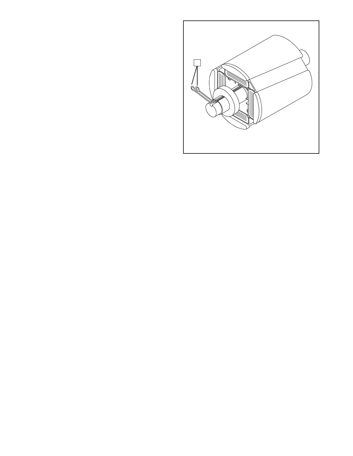
Rotor
Thefour-pole rotor creates the magnetic field needed to
produce alternating current in the stator windings. Prior
to testing, inspect the rotor for visible damage. Check
rotor bearing for noisy operation, excessive wear, and
heat discoloration. Replace orrepair thesecomponents
if any of the above conditions exist.
Check the rotor for continuity and resistance. Measure
the rotor resistance (ohms) between the two rotorleads
(Figure 7-10). See Specifications--Generator in Section
1 for typical readings.
NOTE
Since ohmmeters do vary in their accuracy, use values
in Section 1 as a reference for approximate readings.
Readings must be at room temperature or about 70° F
(21° C). Rotor resistance will vary directly with increase
in temperature.
Tocheckforrotorshortedtoground,adjustohmmeterto
zero ohms. Touch one ohmmeter lead to either rotor
lead and other lead to rotor poles or shaft. Meter should
register no continuity.
1
1. Rotor Leads
Figure 7-10. Rotor Resistance Check
The rotor must be repaired or replaced if any faults are
detected in the previous tests.
 Loading...

