TP-5648 8/93 Controller Troubleshooting 5-3
Stopping
Normal Stop. A normal stop is initiated by rocking the
Start/Stop Switch on the controller front panel to the
Stop position and then releasing the switch. Holding
the switch in the Stop position energizes the GP
relay, causing further, unnecessary heating of the
glow plugs. In the Stop position, the Start/Stop switch
provides a ground through two blocking diodes to
energize the K4 relay (LED4 lights). The normally open
K4A contacts then close, latching the K4 relay in an
energized condition.
Atthe same time,normally closed K4Bcontacts open to
de-energizetheFP(fuelpump)motorandthe K25relay.
The normally open K25 contacts then open to
de-energizetheFS(fuel)solenoid,turningofftheflowof
fuel. With the fuel supply and fuel pump both turned off,
the engine turns off.
With the engine turned off, the generator output decays
andcauses relays K1 and K5 to de-energize (LED1 and
LED5 go out). The normally open K1D contacts then
open, de-energizing the K2 relay (LED2 goes out) and
opening the normally open K2 contacts to interrupt
power to the remaining controller relay circuits,
including relay K4. As a result, the latch-up of the K4
relayisbrokentoreturnthecontrollercircuitstoanormal
pre-start condition.
Emergency Stop. An emergency stop is initiated by
depressing the Emergency Stop Switch on the
controller front panel. The Emergency Stop Switch is
intended only for emergency conditions; the
Start/Stop Switch should be used for normal stops.
Depressing the Emergency Stop Switch (ES) opens the
normally closed ES contacts, interrupting power to the
controllerrelaycircuitstocauseimmediateturnoffofthe
FP (fuel pump) motor and the FS (fuel) solenoid. With
thefuelsupplyandfuelpumpbothturnedoff,theengine
turns off and the generator output decays.
Whenitisactivated,theEmergencyStopSwitchlocksin
the depressed position. Before the set can be started
again,itisnecessarytorotatetheswitchandreleasethe
locking mechanism so the normally closed ES contacts
can close and restore power to the controller circuits.
F
K1F
FROM SAFETY
SHUTDOWN
SWITCHES
K5
K4A
LED4
K4
K2
SDR
K7
K7
K7
K6
OP
WT
HR
BV
K1BK1A V
1.5 A.1.5 A.
HZ
A2
A1
MAIN FIELD
L2
LO
LO
L1
SDR
OVERSPEED
PROTECTION
CIRCUIT BOARD
VOLTAGE
REGULATOR
LED1 LED5
K1 K5
12 VDC
GP
GLOW PLUGS
GP
M
FS
S
10 A.
K25
K25
FP
10 A.
ES
START
STOP/
PREHEAT
K1C
K1D
K1E
K2
K20
K3
K4B
K2
K3
K20
S
B.C.
ALT
LED3
LED2
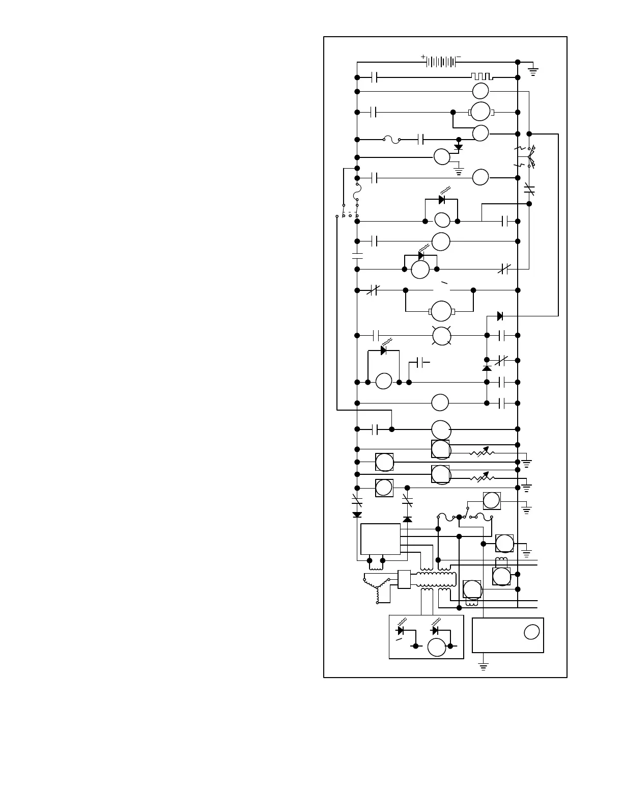
Figure 5-3. Sequence of Operation, Stopping
 Loading...

