Component Testing and Adjustment 7-19TP-5606 6/02
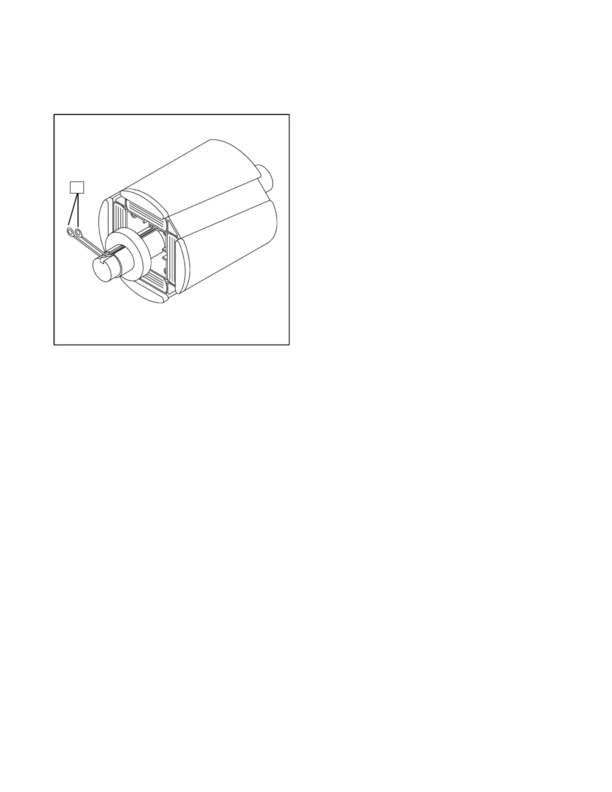
To check for rotor shorted to ground, adjust ohmmeter
to zero ohms. Touch one ohmmeter lead to either rotor
lead and other lead to rotor poles or shaft. Meter should
register no continuity.
1
1. Rotor Leads
Figure 7-15. Rotor Resistance Check
The rotor must be repaired or replaced if any faults are
detected in the previous tests.
Stator
The stator consists of a series of coils of wire placed in a
laminated steel frame. The stator leads supply voltage
to the AC load and exciter regulator.
Prior to testing, inspect the stator for heat discoloration
and visible damage to housing lead wires, exposed coil
windings, and exposed and varnished areas of frame
laminations. Be sure the stator is securely riveted in the
stator housing.
Checking Single-Phase Stator
Continuity and Resistance
1. To check stator continuity, set ohmmeter on R x 1
scale. Contact the red and black meter leads;
adjust ohmmeter to zero ohms. Check stator
continuity by connecting meter leads to stator
leads as shown in Figure 7-16.
NOTE
Disconnect all stator leads prior to performing
stator continuity tests.
Leads 1, 2, 3, and 4 are the generator output leads.
Leads 33 and 44 are the voltage regulator sensing
leads. Leads 33 and 55 are the voltage regulator power
supply. Leads B1 and B2 are the generator output
interlock circuit for the controller. Refer to the schematic
in Figure 7-17 when performing the following tests.
 Loading...


