TP-5606 6/025-6 Controller Troubleshooting
Running
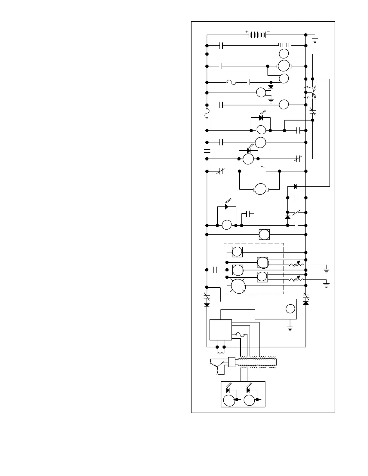
During engine start-up, flashing current is provided to
the generator exciter field through a normally open
contact of the K2 relay and normally closed contacts of
the K1 relay. The resulting generator output from the
B1/B2 stator winding, rectified and regulated to a 12
VDC level, energizes the K1 relay (LED1 lights). After a
5- to 10-second delay, the K5 relay is energized (LED5
lights). Both relays remain energized during normal
running.
Energizing the K1 relay opens the normally closed K1A
and K1B contacts that supply flashing current to the
generator exciter field. Field exciter current for
continued operation is then supplied by the voltage
regulator, operating from an input supplied by generator
stator winding 55/66.
Energizing the K1 relay opens the normally closed K1C
contacts between the Start/Stop switch and the K2 relay
in the engine start-up circuit. However, at the same time,
the normally open K1D contacts close to keep the K2
relay energized. Energizing K1 also closes the normally
open K1F contact to activate BV, OP, HR, WT, and Gen.
on light on the remote panel.
Energizing the K1 relay opens the normally closed K1E
contacts to de-energize the K3 relay. As a result, K20
and the S (Starter) solenoid de-energize to disengage
and de-energize the starter motor, even when the
Start/Stop switch is held in the Start position. The other
devices energized during engine starting, that is relay
K25, the fuel pump, and the fuel solenoid, remain
energized to keep the engine running and to supply
excitation to the B.C. Alt (battery-charging alternator).
FROM SAFETY
SHUTDOWN
SWITCHES
K5
K4A
LED4
K4
K2
SDR
12 VDC
AH
AIR HEATER
AH
M
FS
S
10 A.
K25
K25
FP
10 A.
START
STOP/
PREHEAT
K1C
K1D
K1E
K2
K20
K3
K4B
K2
K3
K20
S
B.C.
ALT
LED3
LED2
OP
WT
HR
K1A
VOLTAGE
REGULATOR
LED1 LED5
K1 K5
HR
BV
GEN
ON
REMOTE PANEL
K1F
K1B
SDR
OVERSPEED
PROTECTION
CIRCUIT BOARD
MAIN FIELD
8A.
Figure 5-6. Three-Phase Generator Sequence of
Operation, Running
 Loading...


