Disassembly/Reassembly 8-1TP-5606 6/02
Section 8. Disassembly/Reassembly
Prior to disassembly, the generator set must be unbolted
from the vehicle compartment. Disconnect all external
connections—battery cables at battery (negative lead
first), AC output leads in controller, remote start panel at
controller connector, fuel line at fuel pump filter inlet, and
exhaust connections. Observe all safety precautions
listed at the beginning of this manual during the
disassembly/reassembly procedure.
NOTE
Several models are covered in this manual and the
procedure for disassembly/reassembly may vary due to
product updates and assembly variations. Major
differences are noted where appropriate.
NOTE
HARDWARE DAMAGE! Engine and generator may
make use of both American Standard and metric
hardware. Be sure to use the correct size tools to
prevent rounding of bolt heads and nuts.
Single-Phase Generator
Disassembly
NOTE
The voltage regulator is located in the junction box on
these models. Adjustments are possible without
removing the junction box or controller.
1. Remove the mounting screws securing the
controller cover. Separate the cover from the
controller. See Figure 8-1.
1-932
Figure 8-1. Removing the Controller Cover
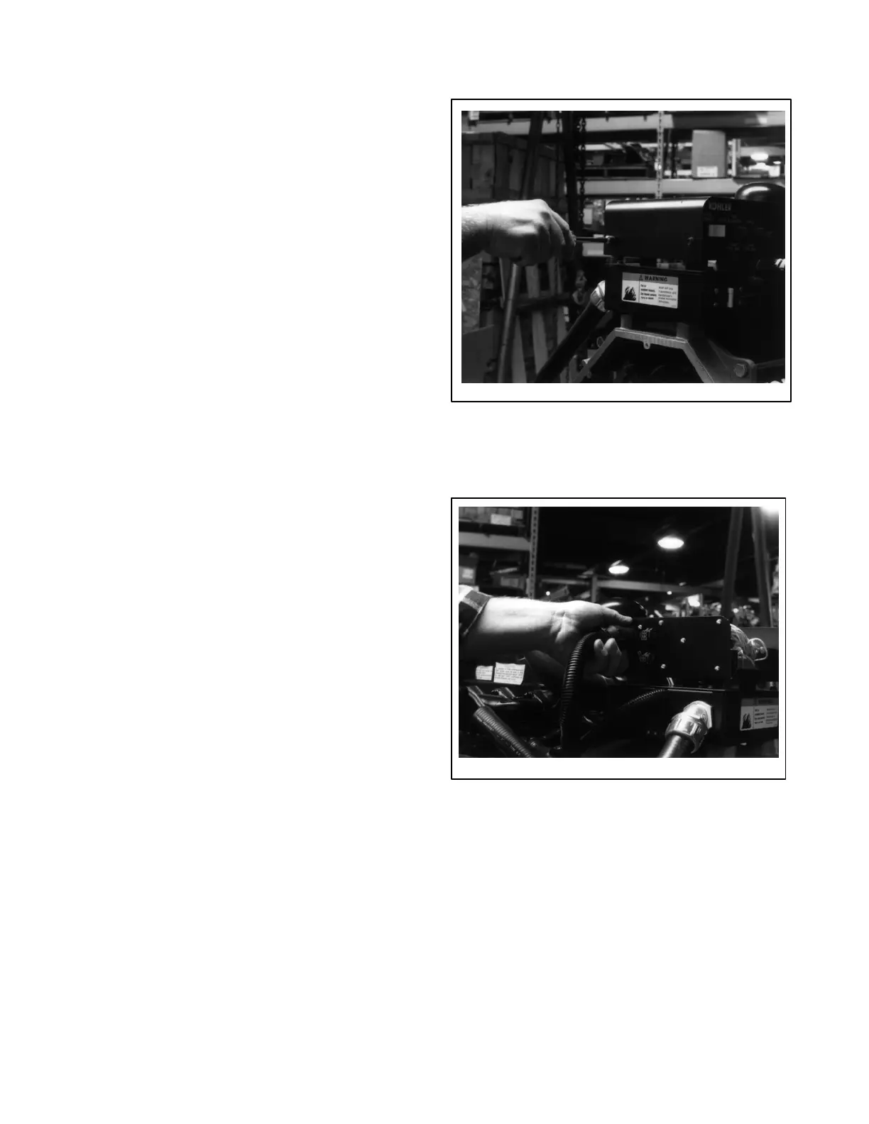
2. Disconnect the 22-pin controller harness (P4)
located at the back of the controller. See
Figure 8-2.
1-932
Figure 8-2. Disconnecting the 22-Pin Connector
 Loading...


