TP-5606 6/02 Controller Troubleshooting 5-1
Section 5. Controller Troubleshooting
Data in this section describes the controller sequence of
operation during starting, running, and stopping of the
generator set. The controller for a single-phase
generator is different than the controller for a
three-phase generator. Therefore, separate sequence
of operation information is provided for single-phase
and three-phase generators. Use this data as a starting
point for controller fault identification.
Single-Phase Generator
Sequence of Operation
Starting
Preheating—A heater mounted on the intake manifold
is used to preheat intake air during starting in cold
weather. Preheating is initiated by rocking the Start/Stop
switch on the control panel to the STOP/PREHEAT
position for the time period specified in Section 2. This
action energizes the C1 relay. As a result, normally open
contacts of the C1 relay close to energize the air heater.
At the end of the specified time period, the Start/Stop
switch is released or rocked out of the STOP/PREHEAT
position. Either of these actions opens the ground path
to the C1 relay, de-energizing the C1 relay and the air
heater.
Engine Start-up—The engine is started by rocking the
start/stop switch on the control panel to the START
position. At this point, the 10-ampere fuse must be good.
If not, power to the starting circuits is interrupted and
none of the following actions described below occur.
Setting the Start/Stop switch to the START position
energizes the K2 relay (LED2 lights). As a result,
normally open contacts of K2 close to energize the K3
relay, the K25 relay, and the FP (Fuel Pump) motor.
Energizing the K3 relay (LED3 lights) causes a set of
normally open contacts to close and energize relay K20.
A set of normally open contacts of K20 then close to
energize the S solenoid (Starter Solenoid). As a result,
normally open contacts of the S relay close to energize
the M (starter) motor and the starter motor gear engages
the ring gear on the engine flywheel to begin cranking
the engine. At the same time, the power supplied to the
starter motor also energizes the pull-in coil of the FS
(Fuel Supply) Solenoid.
Energizing the K25 relay closes a set of normally open
contacts to energize the hold coil of the fuel solenoid to
complete the conditions necessary for engine start-up.
For units with remote radiators, energizing K2 also
energizes the K30 relay. Energizing the K30 relay closes
a set of normally open contacts to energize a 12 VDC
fan. This fan provides cooling for the remote radiator.
Releasing the Start/Stop switch allows the switch to
return to its neutral position. If the switch is released
before the engine starts (the K1 relay is still
de-energized), the K2 relay de-energizes. The normally
open contacts of the K2 relay then open to interrupt
power to the engine start-up circuits. As a result the K3
relay, the K25 relay, the K20 relay, the K30 relay, the
Fuel Pump, the Fuel Solenoid, and the Starter Solenoid
all de-energize to cease start-up of the engine.
TO REMAINING
CIRCUITS
12 VDC
AIR HEATER
C1
M
FS
S
10 A.
K25
K30
FP
10 A.
START
STOP/
PREHEAT
K1C
K1D
K1E
K2
K3
K3
K2
K20
S
B.C.
ALT
LED3
LED2
C1
15 A.
K30
12VDC
FAN
K25
K4B
K20
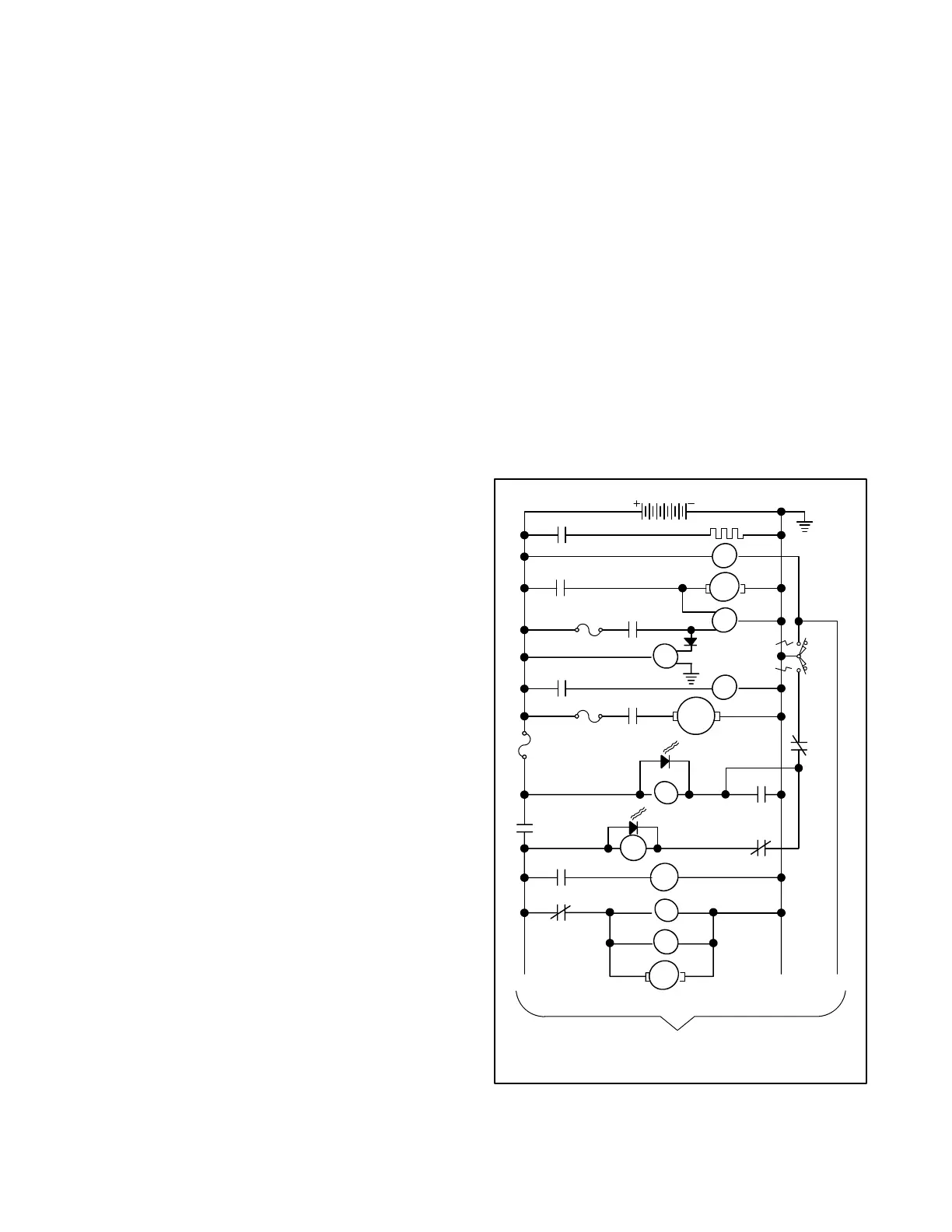
Figure 5-1. Single-Phase Generator Sequence of
Operation, Starting
 Loading...


