TP-5606 6/02 Wiring Diagrams 9-5
Twelve-Lead (Three-Phase) Generator Sets
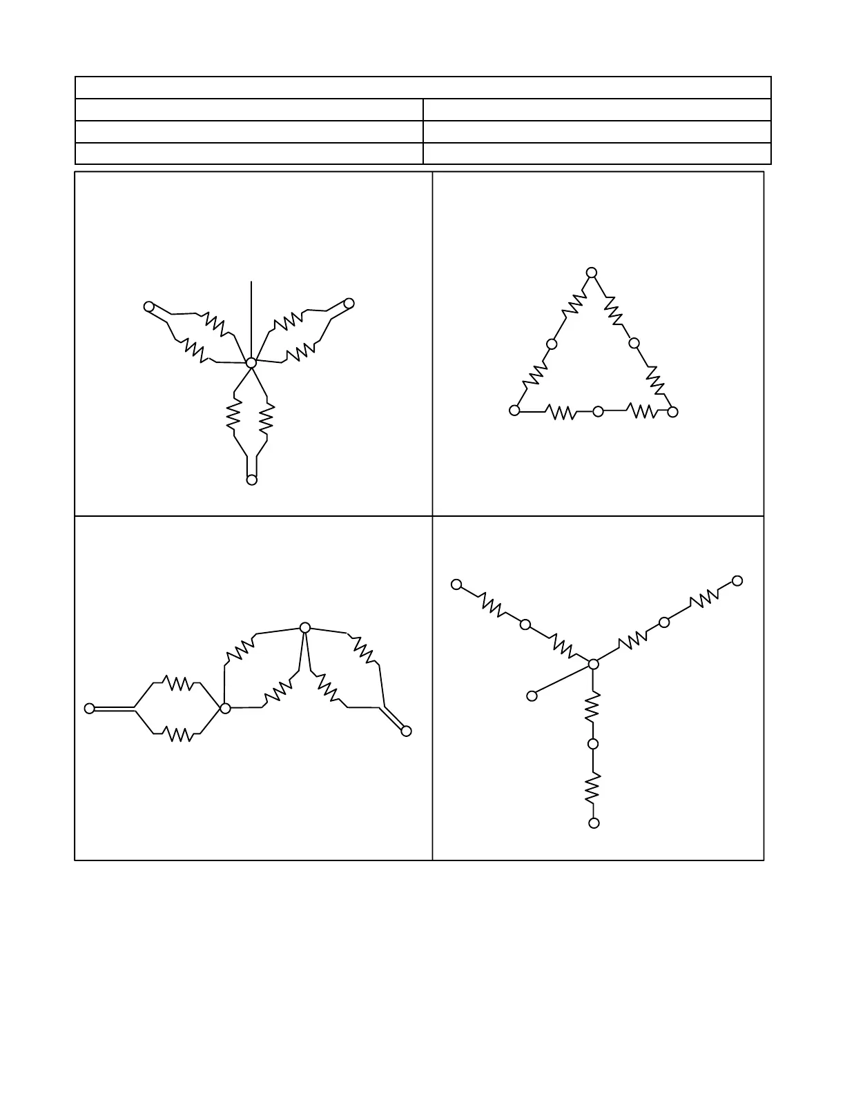
Diagrams provided to support this configuration are as follows:
Output Wiring Figure 9-5
Schematic Wiring Diagram (Three-Phase Models) Figure 9-6
Point-to-Point Wiring Diagram (Three-Phase Models) Figure 9-7
L1
1
4
710
L0
6
3
9
12
11
8
5
2
L2
60 Hz--120/240 volt, 1 PH. 3 WIRE
50 Hz--110/220 volt, 1 PH. 3 WIRE
8
11
1
4
L2
7
10
L1
6
3L3
L0
12 LEAD STATOR
60 Hz--120/208 volt or 139/240 volt
3 PH. 4 WIRE LOW WYE
50 Hz--120/208 volt or 110/190 volt
3 PH. 4 WIRE LOW WYE
L2
L1 L3
8
11
2
5
12
9
91236
7
10
1
4
12 LEAD STATOR
60 Hz--120/240 volt, 3 PH. 4 WIRE DELTA
50 Hz--110/220 volt, 3 PH. 4 WIRE DELTA
L0
L2
L1
L3
8
11
2
5
9
12
3
6
7
10
1
4
L0
L0
12 LEAD STATOR
60 Hz--277/480 volt, 3 PH. 4 WIRE HIGH WYE
50 Hz--220/380 volt, 3 PH. 4 WIRE HIGH WYE
5
2
Figure 9-5. Three-Phase Voltage Reconnections
 Loading...


