TP-5606 6/029-4 Wiring Diagrams
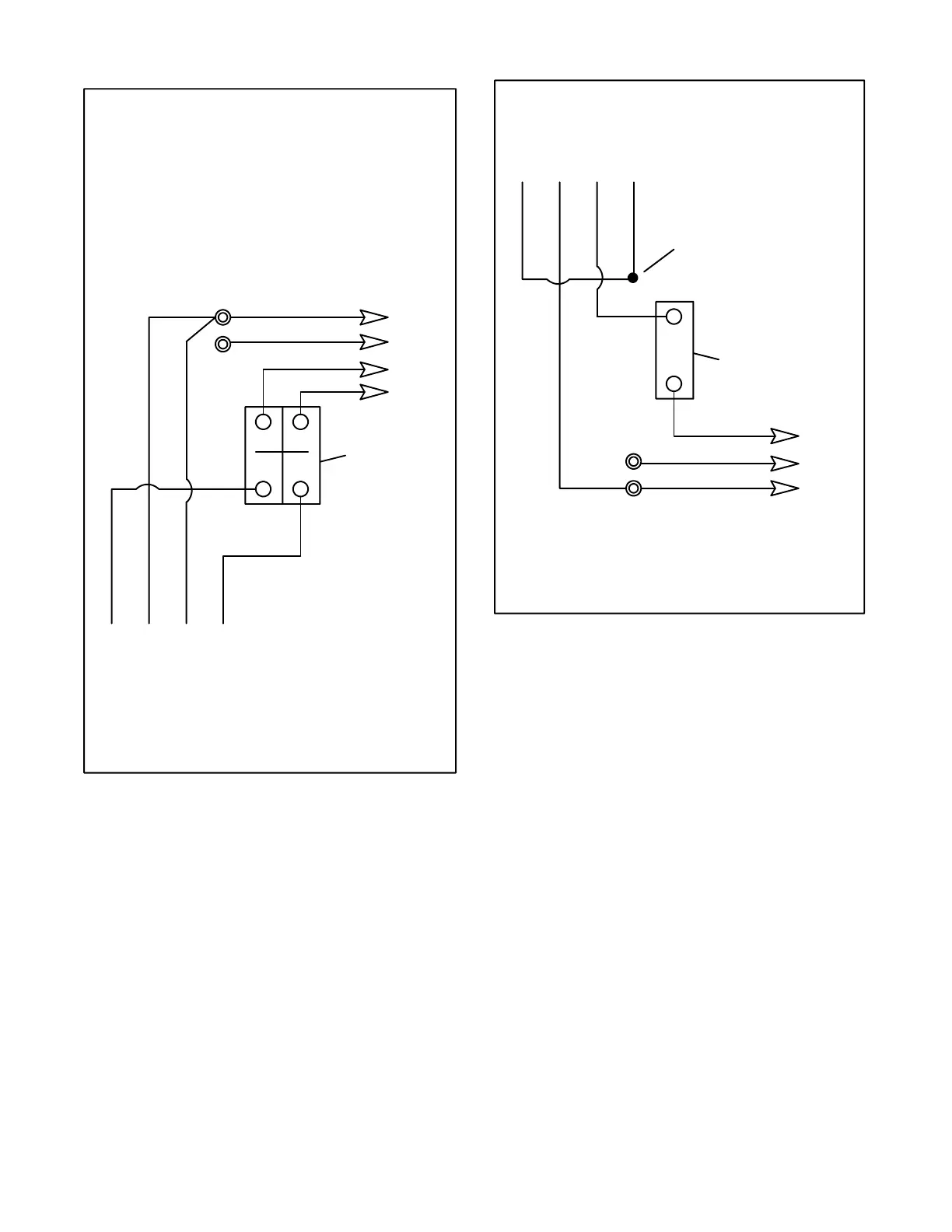
4321
Stator Leads
LO
GRD.
L2
L1
LO (Neutral)
Line
Side
Factory
Two-Pole
Circuit
Breaker
Ground
Load
Side
120/240 Volt, 3 Wire
Circuit breaker MUST be a circuit breaker
manufacturer two-pole circuit breaker. Two
single-pole circuit breakers do not conform to NEC
requirements when supplying a 240-volt (or 220-volt)
load. This is true even if they are mechanically
attached together. Leads L1 and L2 are different
phases and must never be connected together.
Leads 60Hz 50Hz
L0-L1 120 volt 110 volt
L0-L2 120 volt 110 volt
L1-L2 240 volt 220 volt
Figure 9-3. Output Wiring, 120/240-Volt (or
110/220-Volt, 100/200-Volt) Configurations
4321
Stator Leads
LO
GRD.
L1
LO (Neutral)
Line
Side
Single-Pole
Circuit
Breaker
Ground
Load
Side
Tape to insulate
from ground
Leads 60Hz 50Hz
L0-L1 not used 200--240 volt
This system uses a single-pole circuit breaker with
200--240 Volt, 2 Wire.
Figure 9-4. Output Wiring, 200--240-Volt
Configurations
 Loading...


