8-8 Disassembly/Reassembly TP-5606 6/02
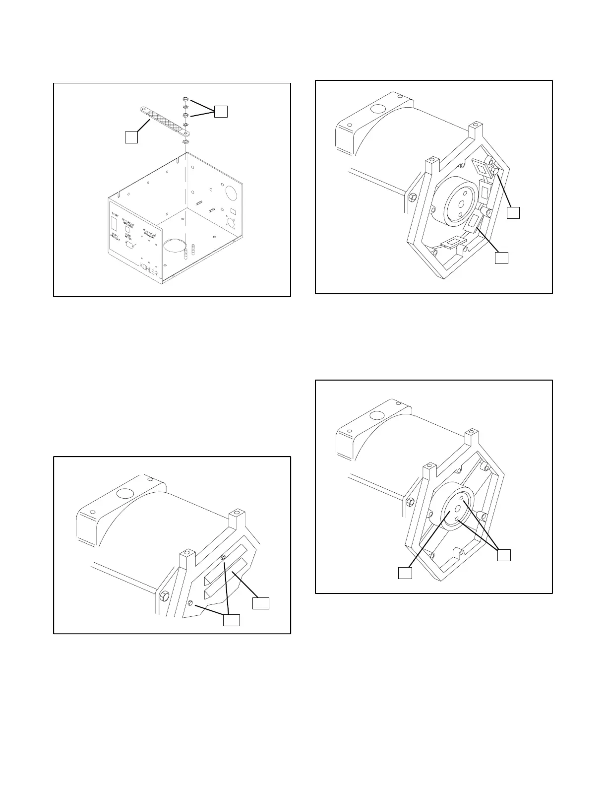
5. Remove the nuts using a 3/8-inch wrench and
disconnect the ground strap from the controller.
See Figure 8-22.
1
1. Ground Strap 2. Nuts
2
Figure 8-22. Disconnecting the Controller
Ground Strap
6. Remove the controller.
7. Disconnect P8 from J8.
8. Remove the six screws securing the end bracket
panel to the end bracket using a 5/16-inch wrench
or nut driver. Remove the end bracket panel to
expose the exciter. See Figure 8-23.
1
2
1. Screw 2. End Bracket Panel
Figure 8-23. Removing the End Bracket Panel
9. Disconnect P6 from J6 and P7 from J7.
10. Remove the four screws securing the exciter field
to the end bracket. Carefully remove the exciter
field from the generator. See Figure 8-24.
1
2
1. Screw 2. Exciter Field
Figure 8-24. Removing the Exciter Field
11. Remove the three screws and spacers securing
the rotating diode circuit board to the rotor
armature. See Figure 8-25.
1
2
1. Screw 2. Diode Circuit Board
Figure 8-25. Removing the Diode Circuit Board
12. Remove the five screws securing the leads to the
rotating diode circuit board. Carefully separate the
rotating diode circuit board from the rotor
assembly.
 Loading...


