TP-5606 6/02 Operation 2-9
Remote Start and
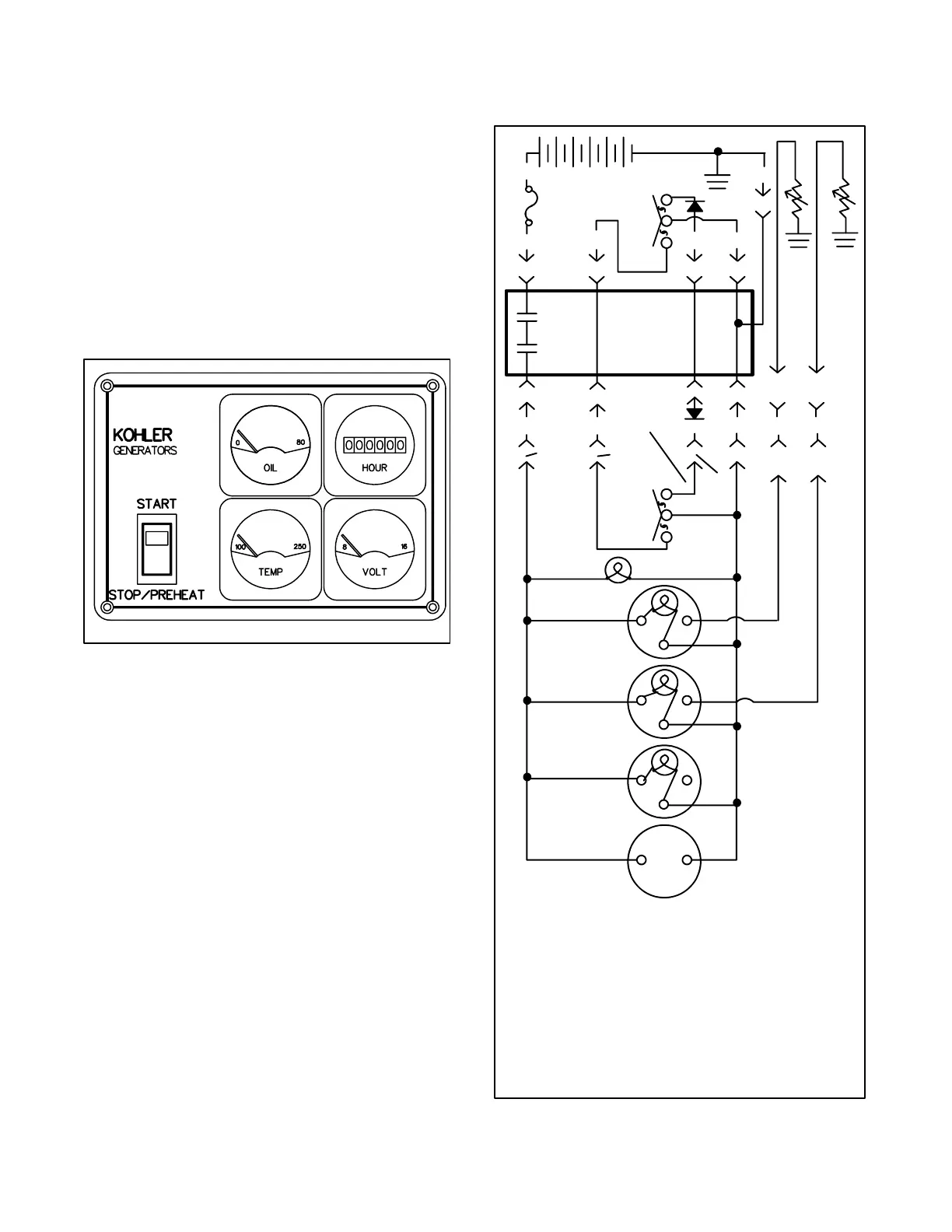
Four-Meter Panel Kit
Allows starting/stopping from a location remote of the
generator set. The illuminated gauges include a DC
voltmeter, engine oil pressure gauge, water
temperature gauge, and generator running time
hourmeter which records total generator set operating
hours. Generator sets come equipped with a 6-pin
connector on controller back panel for connection of the
kit. Overall dimensions are 9 in. (229 mm) by 6 in. (152
mm) with a minimum depth of 4 in. (102 mm). Requires
Remote Connection/Extension Harness and sender kit.
See Figure 2-10 and Figure 2-11 for remote start and
four-meter panel features.
TT-873
Figure 2-10. Remote Start and
Four-Meter Panel Features
Start-Stop/Preheat Switch--Rocker-type switch with
“ON” light used to start and stop the generator set.
During cold weather starts (below 50_F[10_C]):
Place controller start switch in STOP/PREHEAT
position for 15--20 seconds before attempting to start
generator set. This provides energizing of the glow
plugs.
DC Voltmeter--Measures voltage of starting
battery(ies). Normal battery operating range is 12--14
Volts.
Engine Oil Pressure Gauge--Measures engine oil
pressure. Normal engine operating range is 36--50 psi
(248--345 kPa).
NOTE
During the engine break-in period, it is normal for the
engine to produce higher oil pressure readings.
Water Temperature Gauge--Measures engine coolant
temperature. Normal engine operating range is
180--205° F (82--96° C).
Hourmeter--Records total generator set operating
hours for reference in maintenance scheduling.
TT-873
Start
P
P
11(7C)
K1
53(70)
3(47) 2(43) 4(N)
Hourmeter
DC Voltmeter
Oil Pressure
Gauge
Water Temp.
Gauge
Gen. ‘ON’
Light
Remote
Switch
10(5)
P3-4
(P3-5)
P3-5
(P3-6)
P3-1
P3-3
(P3-2)
P3-6
(P3-3)
P2-3
P2-7
P2-8
P2-9
P4-13
(P4-2)
P4-10
(P4-3)
K2
P1-14
3(47)
P2-4
2(43)
P2-5 P2-6
4(N)
P1-9
N
+-
Relay
Circuit
Board
Local
Switch
Violet
Tan
Black
Yellow/
Red
Grey/
Black
L.
Blue
Start
Stop/
Preheat
Stop/Preheat
10 A.
Fuse
P3-2
(P3-4)
W.T .
Sender
O.P.
Sender
NOTE
When the Start-Stop/Preheat
Switch is in the Start position,
contacts 3 and 4 are closed.
NOTE
Wire and pin numbers for
single-phase systems may differ
from those for three-phase systems,
where they are different, the
single-phase numbers are shown
first followed by the three-phase
numbers in parentheses.
Figure 2-11. Remote Start & Four-Meter Panel Kit
 Loading...


