Electrical System
32 62 690 02 Rev. DKohlerEngines.com
Fixed Ignition System
This system uses a capacitive discharge (CD) coil. Ignition timing and spark remains constant regardless of engine
speed. Timing of spark is controlled by location of fl ywheel magnet group as referenced to engine TDC. A typical fi xed
ignition system consists of:
● 1 magnet assembly which is permanently affi xed to fl ywheel.
● 2 electronic capacitive-discharge ignition modules which mount on engine crankcase.
● 1 kill switch (or key switch) which grounds modules to stop engine.
● 2 spark plugs.
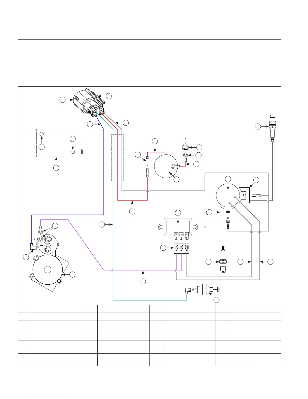
Wire Diagram-15/20/25 Amp Regulated Battery Charging System with Fixed Timing, Four Pin Connector
B
H
G
D
R
B
S
J
P
L
Q
W
E
V
C
T
O
U
A
VM
M
F
B
I
K
N
O
A Blue B Red C Green D Violet (Charging)
E White (Ignition Kill) F Connector G Battery H Battery Positive
I Battery Negative J Starter K Rectifi er-Regulator L Oil Sentry
™
M Spark Plug(s) N
Flywheel Stator
Assembly
O Ignition Module(s) P Carburetor
Q
Intake Manifold
Screw
R Starter Solenoid Stud S Ground T
Rectifi er-Regulator
Connector
U
Starter Solenoid
Tang
V
White
(AC Charging Leads)
W Polarity Ribs X Solenoid Lead
X