Disassembly/Inspection and Service
54 62 690 02 Rev. DKohlerEngines.com
Remove Governor Gear Assembly
Governor gear is held onto shaft by small molded tabs
in gear. When gear is removed from shaft, these tabs
are destroyed and gear must be replaced. Therefore,
remove gear only if absolutely necessary. If governor
cross shaft, yoke, or gear condition does not require
removal, governor gear may be left in place. If removal is
necessary, perform as follows:
1. Remove locking tab thrust washer and note
orientation.
2. Using a screwdriver, carefully pry upward to unseat
governor gear assembly from governor gear shaft.
Remove regulating pin and governor gear assembly.
3. Inspect governor gear shaft for wear or damage.
Remove shaft only if replacement is needed.
Inspection
Governor gear is located within crankcase. Inspect
governor gear teeth. Replace gear if it is worn, chipped,
or if any teeth are missing. Inspect governor weights.
They should move freely in governor gear.
Remove Governor Yoke, Cross Shaft, and Seal
1. Remove mounting screws securing yoke to governor
cross shaft.
2. Pull governor cross shaft out of crankcase and
remove seal.
Remove Lifter Feed Chamber Cover and Gaskets
Remove screws securing lifter feed chamber cover and
gaskets. Carefully separate parts from crankcase.
Remove Flywheel and PTO End Oil Seals
Remove oil seals from crankcase and oil pan using a
seal puller.
Remove Crankshaft Bearings (fl ywheel/PTO)
NOTE: Bearing should only be removed if replacement
is required due to wear. If removal is performed,
use a press and support casting surface around
bearing fl ange. Do not press against or support
by gasket/outer perimeter surface.
Crankcase
Inspection and Service
Check all gasket surfaces to make sure they are free of
gasket fragments. Gasket surfaces must also be free of
deep scratches or nicks.
Inspect crankshaft bearing (if equipped) for wear
or damage. Replace bearing or crankcase using a
miniblock or short block as required.
Check cylinder bore for scoring. In severe cases,
unburned fuel can cause scuffi ng and scoring of cylinder
wall. It washes necessary lubricating oils off piston and
cylinder wall. As raw fuel seeps down cylinder wall,
piston rings make metal to metal contact with wall.
Scoring of cylinder wall can also be caused by localized
hot spots resulting from blocked cooling fi ns or from
inadequate or contaminated lubrication.
If cylinder bore is badly scored, excessively worn,
tapered, or out-of-round, resizing is necessary. Use
an inside micrometer to determine amount of wear,
then select nearest suitable oversize of either 0.25 mm
(0.010 in.) or 0.50 mm (0.020 in.). Resizing to these
oversizes will allow usage of available oversize piston
and ring assemblies. Initially, resize using a boring bar,
then use following procedures for honing cylinder.
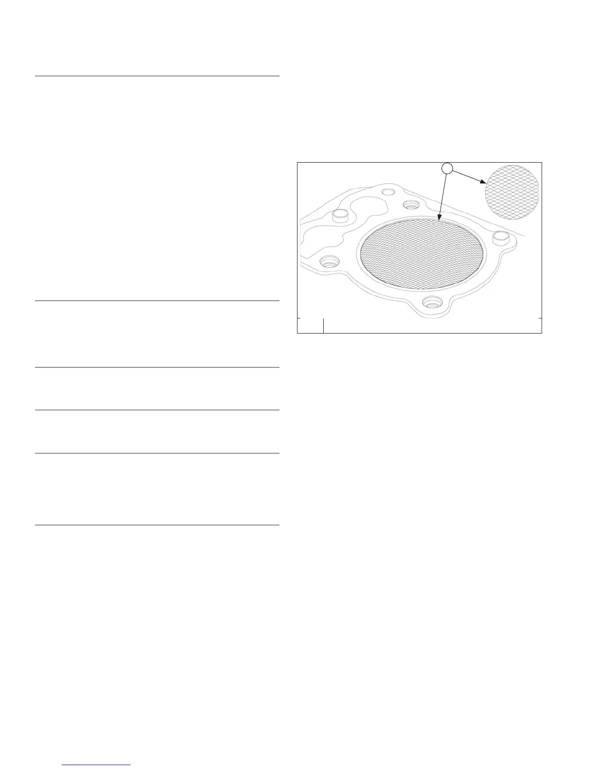
Honing
Detail
A
A 23°-33° Crosshatch
NOTE: Kohler pistons are custom-machined to exacting
tolerances. When oversizing a cylinder, it should
be machined exactly 0.25 mm (0.010 in.) or
0.50 mm (0.020 in.) over new diameter.
corresponding oversize Kohler replacement
piston will then fi t correctly.
While most commercially available cylinder hones can
be used with either portable drills or drill presses, use
of a low speed drill press is preferred as it facilitates
more accurate alignment of bore in relation to crankshaft
crossbore. Honing is best accomplished at a drill speed
of about 250 RPM and 60 strokes per minute. After
installing coarse stones in hone, proceed as follows:
1. Lower hone into bore and after centering, adjust so
stones are in contact with cylinder wall. Use of a
commercial cutting-cooling agent is recommended.
2. With lower edge of each stone positioned even with
lowest edge of bore, start drill and honing process.
Move hone up and down while resizing to prevent
formation of cutting ridges. Check size frequently.
3. When bore is within 0.064 mm (0.0025 in.) of
desired size, remove coarse stones and replace
them with burnishing stones. Continue with
burnishing stones until bore is within 0.013 mm
(0.0005 in.) of desired size and then use fi nish
stones (220-280 grit) and polish bore to its fi nal size.
A crosshatch should be observed if honing is done
correctly. Crosshatch should intersect at
approximately 23°-33° off horizontal. Too fl at an
angle could cause rings to skip and wear
excessively, and too steep an angle will result in high
oil consumption.