Reassembly
62 62 690 02 Rev. DKohlerEngines.com
c. Hold adjuster nut in this position and tighten
locking setscrew. Torque setscrew to 7.3 N·m (65
in. lb.).
d. Repeat procedure for other valve on this side.
4. Viewed from PTO end, rotate crankshaft 270° (3/4
turn) counterclockwise and align crankshaft keyway
with cylinder 2, which now puts that cylinder at TDC
on compression stroke.
5. Repeat steps 3-5 for setting valve clearance on
cylinder 2.
6. Rotate crankshaft to check for free operation of
valve train. Check for clearance between valve
spring coils at full lift, or bending of push rod(s) can
occur. Minimum allowable clearance is 0.25 mm
(0.010 in.).
Check Assembly
Rotate crankshaft a minimum of two revolutions to check
assembly and overall proper operation.
Check if engine can be turned over completely and
compression is noted. If it cannot (locks up at some
point), return piston to TDC between intake and exhaust
strokes fi rst for one cylinder and then other waiting ten
minutes to allow lifters to bleed down, then check for
compression again.
Install Valve Covers
1. Make sure sealing surfaces are clean and free of
any nicks or burrs.
2. Install and properly seat seal onto each valve cover.
3. Install valve covers on same side as they were
originally installed.
4. Install a new grommet on each valve cover mounting
screw. Start each screw into hole.
5. Check position of each cover and seal, then torque
screws to 13.6 N·m (120 in. lb.).
Install Spark Plugs
1. Check gap using wire feeler gauge. Adjust gap to
0.76 mm (0.030 in.).
2. Install plug into cylinder head.
3. Torque plug to 27 N·m (20 ft. lb.).
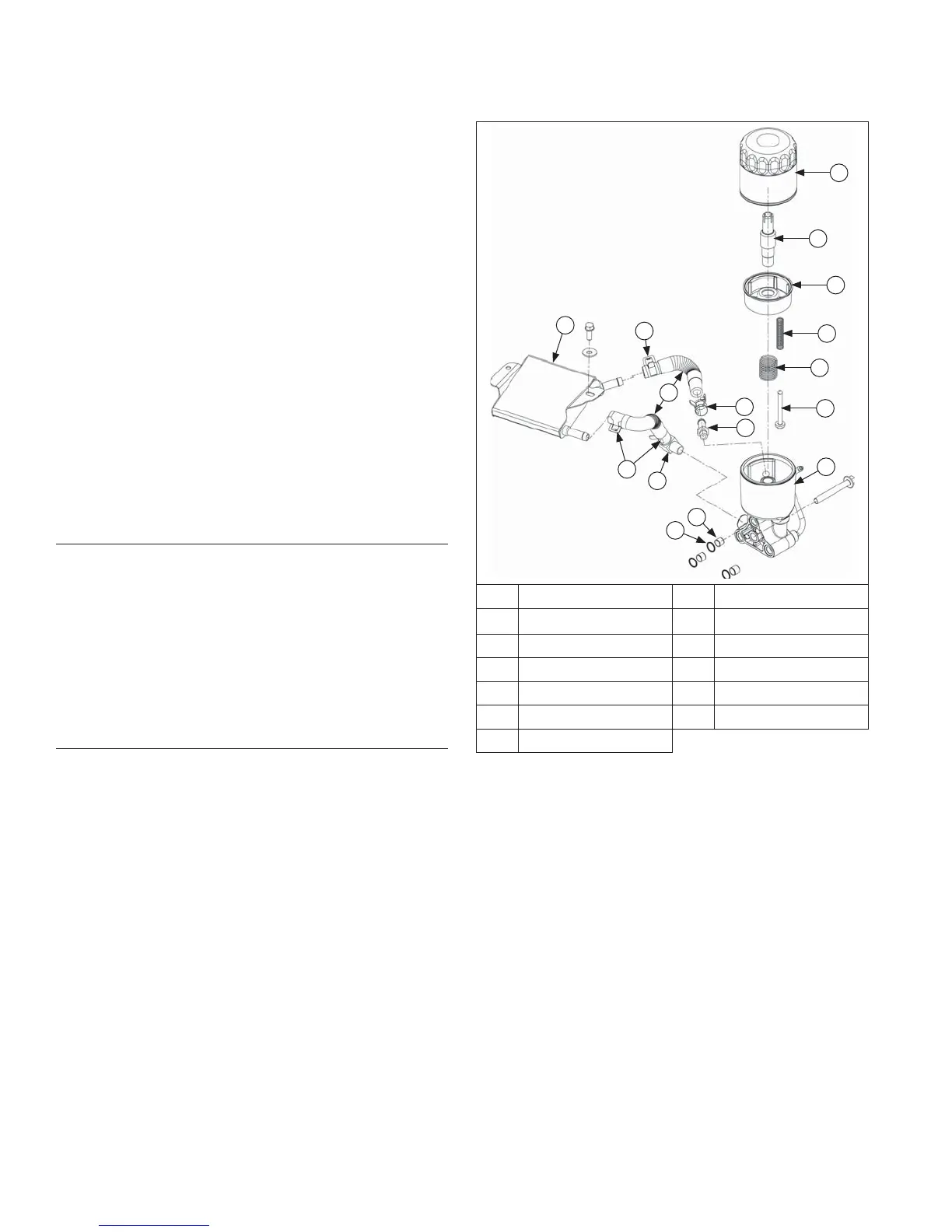
Oil Cooler/Filter Components
A
B
C
D
E
F
G
H
L
K
M
J
K
J
K
I
A Oil Filter B Oil Filter Nipple
C Cup D Valve Spring
E Cup Spring F Oil Filter Valve
G Oil Filter Housing H Pin
I O-Ring J Fitting
K Hose Clamp L Hose
M Oil Cooler