Reassembly
68 62 690 02 Rev. DKohlerEngines.com
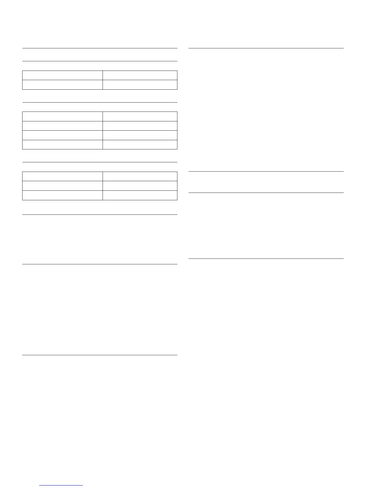
Governor Spring/RPM Chart
CV940-CV1000
Governor Idle Spring (Color) High Speed (RPM)
Clear 1400-1625 RPM
Black 1626-1800 RPM
CV940, CV960, CV980
Governor Spring (Color) High Speed (RPM)
Orange 3000-3100 RPM
Red 3101-3300 RPM
Green 3301-3750 RPM
Purple 3751-3900 RPM
CV1000
Governor Spring (Color) High Speed (RPM)
Orange 3000-3100 RPM
Red 3101-3300 RPM
Purple 3301-3900 RPM
Install Oil Sentry
™
(if equipped)
1. Apply pipe sealant with Tefl on
®
(Loctite
®
PST
®
592™
Thread Sealant or equivalent) to Oil Sentry
™
threads
switch and install it into 1/8 in. port in oil pan. Torque
switch to 10.1 N·m (90 in. lb.).
2. Connect green wire lead to Oil Sentry
™
terminal.
Install Blower Housing and Cylinder Shrouds
1. Install dipstick tube with a new lower O-Ring into
crankcase. Secure with lower mounting screw.
Torque screw to 4.0 N·m (35 in. lb.).
2. Attach lift bracket (if used) onto crankcase with
screws. Torque screws to 9.9 N·m (88 in. lb.).
3. Align and install blower housing. Secure with
screws. Torque screws to 4.0 N·m (35 in. lb.) into
new holes, or 2.0 N·m (18 in. lb.) into used holes.
4. Install cylinder shrouds and secure with screws.
Torque screws to 4.0 N·m (35 in. lb.) into new holes,
or 2.0 N·m (18 in. lb.) into used holes.
Install Muffl er
1. Install new exhaust gaskets onto exhaust studs.
2. Install port liners (if equipped). Attach muffl er and
secure with nuts onto exhaust studs. Torque nuts to
24.4 N·m (216 in. lb.).
3. Install any attaching hardware and brackets. Torque
M6 screws to 9.9 N·m (88 in. lb.), and M8 screws to
24.4 N·m (216 in. lb.).
4. Install spark arrestor (if used).
Install Oil Filter and Add Oil to Crankcase
NOTE: Make sure both oil drain plugs are installed and
torqued to 21.4 N·m (16 ft. lb.). to prevent oil
leakage.
1. Install oil drain plugs. Torque plugs to 21.4 N·m
(16 ft. lb.).
2. Place new fi lter in shallow pan with open end up. Fill
with new oil until oil reaches bottom of threads. Allow
2 minutes for oil to be absorbed by fi lter material.
3. Apply a thin fi lm of clean oil to rubber gasket on new
fi lter.
4. Refer to instructions on oil fi lter for proper
installation.
5. Fill crankcase with new oil. Level should be at top of
indicator on dipstick.
6. Reinstall oil fi ll cap/dipstick and tighten securely.
Connect Spark Plug Leads
Connect leads to spark plugs.
Prepare Engine for Operation
Engine is now completely reassembled. Before starting
or operating engine, follow proceeding steps.
1. Make sure all hardware is tightened securely.
2. Make sure oil drain plugs, Oil Sentry
™
pressure
switch, and a new oil fi lter are installed.
3. Adjust carburetor, idle fuel needles, or idle speed
adjusting screw as necessary.
Testing Engine
It is recommended engine be operated on a test stand or
bench prior to installation in equipment.
1. Set engine up on a test stand. Install an oil pressure
gauge. Start engine and check to be certain oil
pressure (20 psi or more) is present. Run engine at
idle for 2-3 minutes, then 5-6 minutes more between
idle and midrange. Adjust carburetor mixture settings
as necessary (as available).
2. Adjust governed idle and high speed (RPM) to
required settings. Make sure maximum engine
speed does not exceed 3900 RPM (no load).