Reassembly
66 62 690 02 Rev. DKohlerEngines.com
2. Align oil cooler with bosses in backing shroud
assembly. Secure screws and washers to 2.2 N·m
(20 in. lb.).
Install Cooling Fan and Debris Screen
CAUTION
Failure to utilize or reassemble debris screen
as designed could result in debris screen
failure and serious personal injury.
1. Position cooling fan onto fl ywheel aligning mounting
locations. Apply a small amount of Loctite
®
243™
Threadlocker to threads and install long mounting
screws. Torque screws to 9.9 N·m (88 in. lb.).
2. Apply a small amount of Loctite
®
243™ Threadlocker
to external threaded section, (unless new parts with
preapplied locking compound are being used).
Thread debris screen hex studs into mounting holes
in fl ywheel. Torque each stud to 9.9 N·m (88 in. lb.).
3. Install stiffener followed by metal debris screen onto
studs. Secure with special washers and mounting
screws using Loctite
®
243™ Threadlocker on
threads. Torque screws to 9.9 N·m (88 in. lb.).
Install Electric Starter
1. Install electric starter motor using screws.
2. Torque screws to 15.3 N·m (135 in. lb.).
3. Connect leads to solenoid.
Install Valley Baffl es
1. Install valley baffl es and secure with mounting
screws. Lower section should fi t under outer baffl e.
Torque M6 screws going into cylinder head to 10.7
N·m (95 in. lb.) for new holes, or 7.3 N·m (65 in. lb.)
for used holes. Start upper M6 screws only if main
control bracket rear supports attach to these screws.
2. Torque M6 screw going into lower blower housing
mounting clip to 2.5 N·m (22 in. lb.).
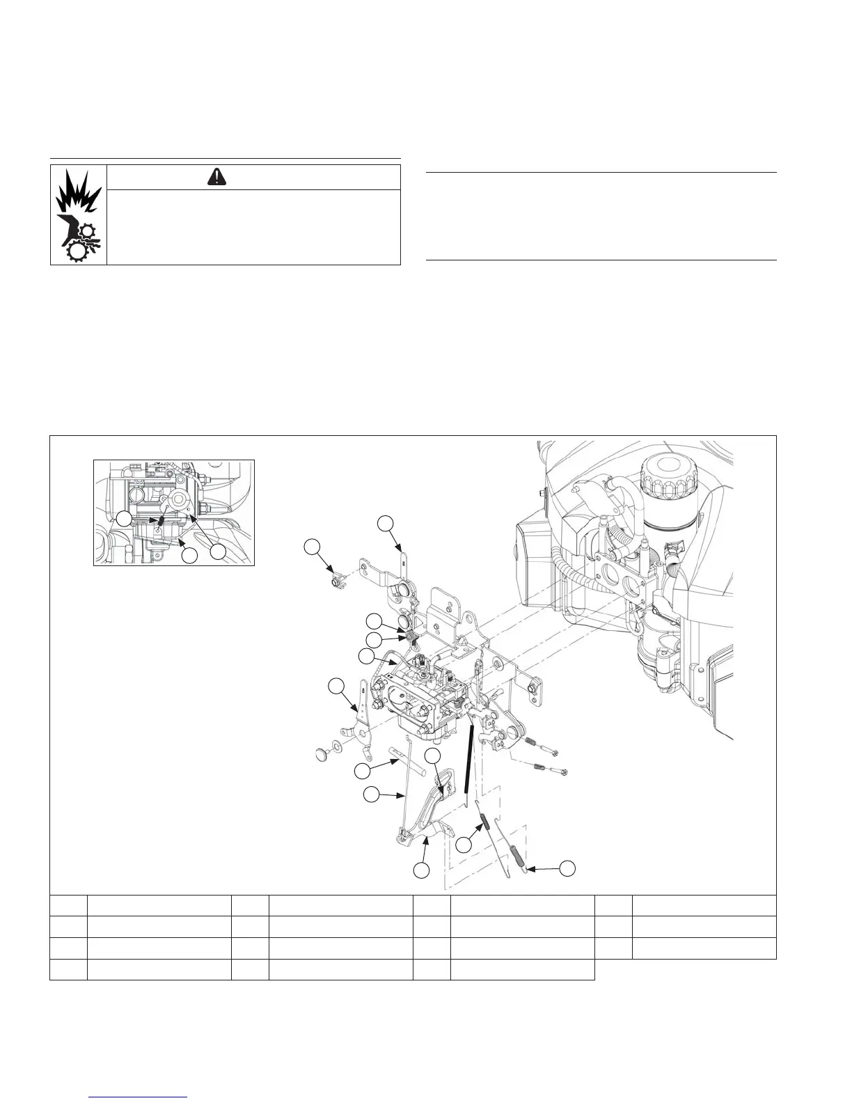
Control Bracket Components
G
E
F
A
I
H
N
M
O
C
D
B
K
L
J
A Throttle Lever B Throttle Linkage C Nut D Governor Arm
E Governor Spring F Governed Idle Spring G Cross Shaft H Governor Lever
I Choke Cable Clamp J Control Pivot Pin K Pal Nut L Choke Linkage
M Choke Return Spring N Choke Bracket O Choke Lever