Disassembly/Inspection and Service
5362 690 02 Rev. D KohlerEngines.com
2. Middle compression ring (center groove): Install
center ring using a piston ring installation tool. Make
sure identifi cation mark is up or colored dye stripe (if
contained), is to left of end gap.
3. Top compression ring (top groove): Install top ring
using a piston ring expander. Make sure
identifi cation mark is up or colored dye stripe (if
contained), is to left of end gap.
Remove Crankshaft
NOTE: If crankpin is reground, visually check to ensure
that fi llet blends smoothly with crankpin surface.
Carefully pull crankshaft from crankcase. Note thrust
washers and shims if used.
Inspection and Service
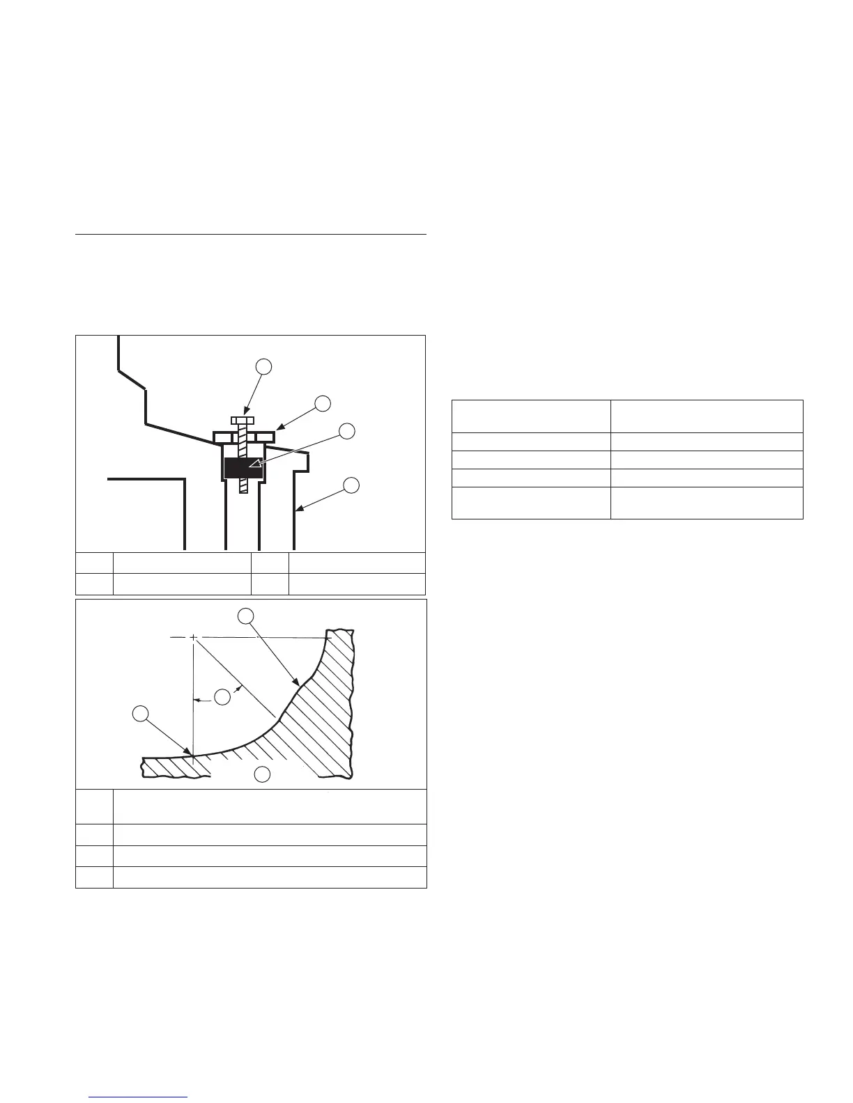
Crankshaft Components and Details
A Self-Tapping Screw B Flat Washer
C Plug D Crankshaft
A
B
C
D
E
Fillet Must Blend Smoothly with Bearing Journal
Surface
F High Point from Fillet Intersections
G 45° Minimum
H This Fillet Area Must Be Completely Smooth
E
G
F
H
Inspect gear teeth of crankshaft. If teeth are badly worn,
chipped, or some are missing, replacement of crankshaft
will be necessary.
Inspect crankshaft bearing surfaces for scoring,
grooving, etc. Replaceable bearings are used in
crankshaft bore of oil pan and/or crankcase. Do not
replace bearings unless they show signs of damage
or are out of running clearance 0.040/0.167 mm
(0.0015/0.0065 in.). If crankshaft turns easily, without
noise, and there is no evidence of scoring, grooving,
etc., on races or bearing surfaces, bearings can be
reused.
Inspect crankshaft keyways. If they are worn or chipped,
replacement of crankshaft will be necessary.
Inspect crankpin for score marks or metallic pickup.
Slight score marks can be cleaned with crocus cloth
soaked in oil. If wear limits, as stated in Clearance
Specifi cations, are exceeded, it will be necessary to
replace crankshaft or regrind crankpin to 0.25 mm
(0.010 in.) undersize. If reground, a 0.25 mm (0.010 in.)
undersize connecting rod (big end) must then be used to
achieve proper running clearance. Measure crankpin for
size, taper, and out-of-round.
Clearance Specifi cations-Connecting Rod Journal
O.D. - New 43.982/44.000 mm
(1.731/1.732 in.)
O.D. - Max. Wear Limit 43.97 mm (1.731 in.)
Max. Taper 0.018 mm (0.0007 in.)
Max. Out-of-Round 0.025 mm (0.0010 in.)
Width 53.00/53.09 mm
(2.0866/2.0901 in.)
Connecting rod journal can be ground 1 size under.
When grinding a crankshaft, grinding stone deposits
can get caught in oil passages, which could cause
severe engine damage. Removing crankpin plug when
crankshaft is ground provides easy access for removing
any grinding deposits that may collect in oil passages.
Use following procedure to remove and replace plug.
Remove Crankshaft Plug
1. Drill a 3/16 in. hole through plug in crankshaft.
2. Thread a 3/4 in. or 1 in. long self-tapping screw with
a fl at washer into drilled hole. Flat washer must be
large enough to seat against shoulder of plug bore.
3. Tighten self-tapping screw until it draws plug out of
crankshaft.
Install New Crankshaft Plug
Use 1 single cylinder camshaft pin, as a driver and tap
plug into plug bore until it seats at bottom of bore. Make
sure plug is tapped in evenly to prevent leakage.