Reassembly
6362 690 02 Rev. D KohlerEngines.com
Install Oil Filter Housing Assembly
Reassemble oil fi lter housing if disassembled previously.
Reassembly
1. Install small spring onto rubber valve, and insert
small end through corresponding hole in cup until
properly seated.
2. Install larger spring into fi lter housing.
3. Insert oil fi lter cup, aligning cutout with
corresponding section in housing.
4. Install nipple in housing and torque to 18 N·m
(159 in. lb.).
Installation
1. Make sure all sealing surfaces are clean and all
dowel pins are in position. Install or check new
O-rings are around all oil fi lter adapter dowel pins.
2. Install oil fi lter housing assembly and secure with M8
screw. Make sure housing is fl at on crankcase and
all O-rings remain in position. Torque screw to
24.4 N·m (216 in. lb.)
3. Oil fi lter may be installed now or upon completion of
engine assembly.
Install Intake Manifold
Torque Sequence
3
1
2
4
1. Install new intake manifold gaskets so notched
section is inward and points toward fl ywheel side.
2. Mount intake manifold to cylinder heads. Make sure
gaskets remain in proper position. Torque screws in
2 stages using sequence shown, fi rst to 16.9 N·m
(150 in. lb.), fi nally to 22.6 N·m (200 in. lb.).
3. Install carburetor mounting studs into intake manifold
if previously removed. Use nuts, locked fl ange to
fl ange, and tighten each stud until bottomed/tight.
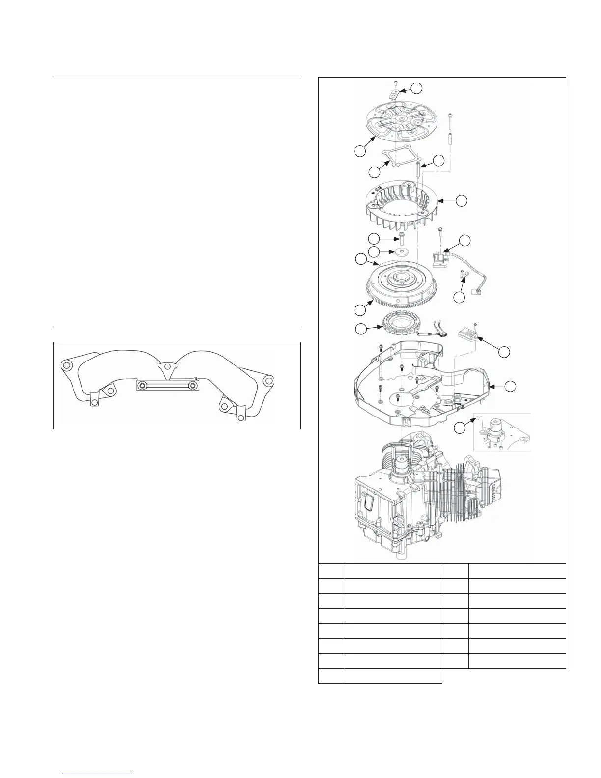
Flywheel/Ignition Components
N
L
K
I
C
D
E
B
A
J
M
H
F
G
O
A Special Washer B Debris Screen
C Hex Stud D Stiffener
E Fan F Flywheel Screw
G Ignition Module H Washer
I Magnet J Wire Harness Clamp
K Flywheel L Stator
M Rectifi er-Regulator N Backing Shroud
O Woodruff Key