Reassembly
6162 690 02 Rev. D KohlerEngines.com
Valve Stem Seals
These engines use valve stem seals on intake and
exhaust valves. Always use new seals whenever valves
are removed from cylinder head. Seals should also be
replaced if worn or damaged. Never reuse an old seal.
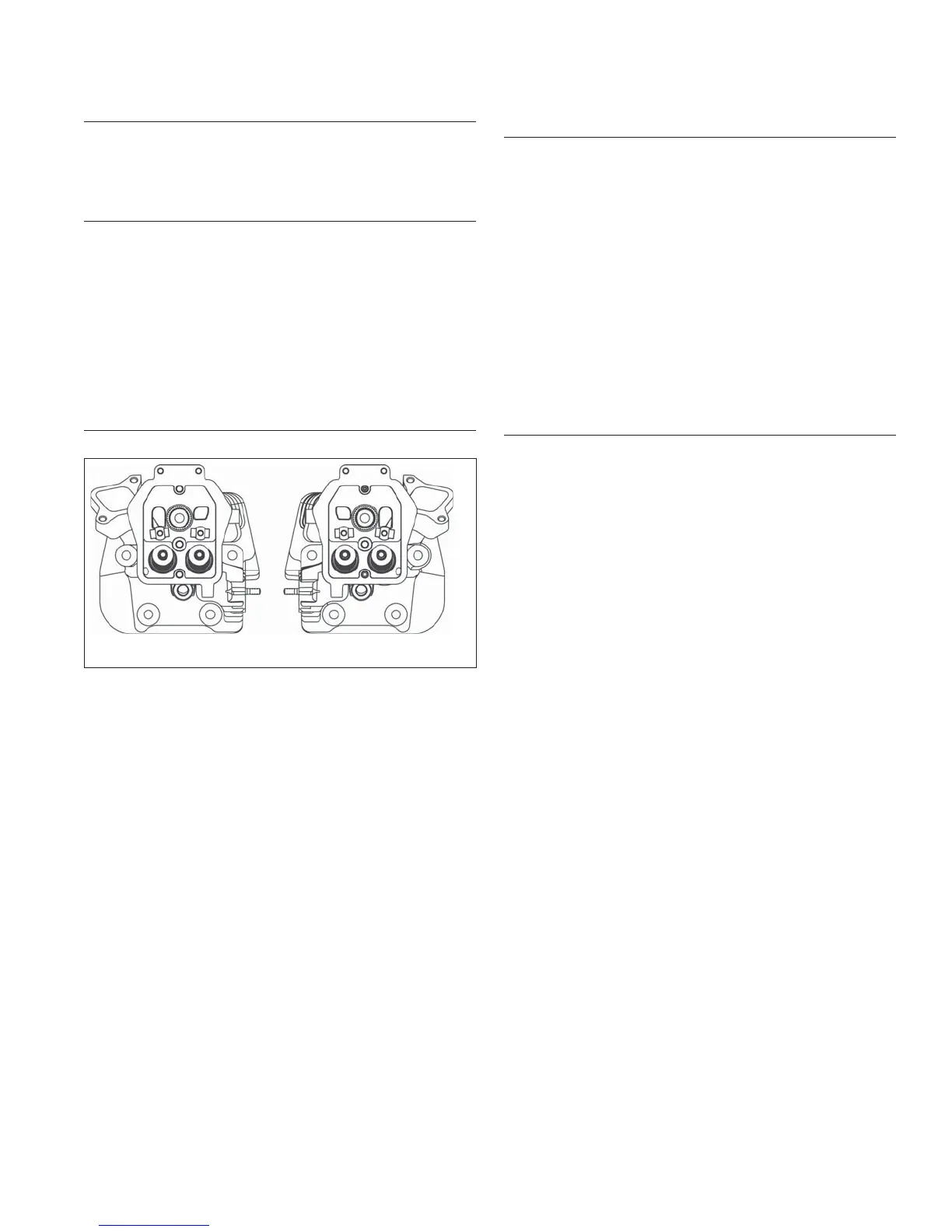
Assemble Cylinder Heads
Prior to installation, lubricate all components with engine
oil, paying particular attention to lip of valve stem seal,
valve stems, and valve guides. Install in order listed
below using a valve spring compressor.
● Intake and exhaust valves
● Valve spring retainers.
● Valve springs.
● Valve spring keepers.
● Valve stem seals.
● Guide plate.
● Pivot studs.
Install Cylinder Heads
Torque Sequence
12
2
2
4
4
5
5
3
3
1
1
NOTE: Match numbers embossed on cylinder heads
and crankcase.
1. Check to make sure there are no nicks or burrs on
sealing surfaces of cylinder head or crankcase.
2. Check dowel pins are in place in 2 lower locations,
and install a new cylinder head gasket, (printed side
up).
3. Install cylinder head. Make sure head is fl at on
gasket and dowel pins. Install a fl at washer on
screws in locations 1 and 3. Install spacer followed
by a fl at washer on screw in location 5. Start 5
screws.
4. Torque screws in 2 stages, fi rst to 22.6 N·m
(200 in. lb.), fi nally to 45.2 N·m (400 in. lb.) following
sequence shown.
5. Repeat procedure for opposite cylinder.
6. Make sure threads of pipe plugs for cylinder heads
are clean and dry. Install a plug into each cylinder
head above screw on location 2 and torque to
28.25 N·m (250 in. lb.).
Install Guide Plate, Pivot Studs, Push Rods and
Rocker Arms
NOTE: Install push rod guide plate so fl ange is down
(towards cylinder) on side 1, and up (away from
cylinder) on side 2.
NOTE: Push rods should always be installed in same
position as before in disassembly.
1. Install push rod guide plate and rocker arm pivot
studs onto cylinder heads if removed previously.
Torque studs to 11.3 N·m (100 in. lb.).
2. Note mark or tag identifying push rod as either
intake or exhaust and cylinder 1 or 2. Dip ends of
push rods in engine oil and install, making sure each
push rod ball seats in its hydraulic lifter socket.
3. Apply grease to contact surfaces of rocker arms and
rocker arm pivots. Install rocker arms, rocker arm
pivots, and adjusters on cylinder head 1.
Adjust Valve Clearance
NOTE: It takes two hands to make lash adjustment. A
clamping device or an assistant to hold lifter
compressed while making adjustment will make
process easier.
1. Turn adjusters in rocker arms by hand clockwise
(down), only enough to capture push rods in
recesses.
2. Rotate crankshaft to establish TDC on compression
stroke for cylinder 1.
Check for:
a. Compression will be felt through spark plug hole.
b. Keyway of crankshaft will be aligned with cylinder
1.
c. No rocker arm/push rod movement if crankshaft
is rotated slightly back and forth. If they are
moving, rotate crankshaft one full revolution.
3. Pre-Bled Lifters:
a. Apply downward pressure to push rod side of
rocker arm to compress lifter and bottom internal
plunger. Several manual compressions may be
necessary. Hold in this position for step 3b.
b. Insert a 0.127 mm (0.005 in.) feeler gauge
between end of one valve and rocker arm. Turn
adjuster until a slight drag is felt. Hold adjuster in
this position and tighten locking setscrew. Torque
setscrew to 7.3 N·m (65 in. lb.). After tightening
recheck adjustment. Proper valve clearance is
0.101/0.152 mm (0.004/0.006 in.).
c. Repeat procedure for other valve on this side.
Non-Bled Lifters (when cylinder heads and lifters are
not removed):
a. Turn 1 rocker arm adjusting nut from side 1 down
until push rod is snug but can be rotated with
drag. This is 0 lash.
b. Mark or note setting of adjustment nut, then turn
(tighten) adjuster nut 4 complete revolutions
clockwise, plus one fl at of nut (1/6 turn), or a total
of 4-1/6 turns.