Disassembly/Inspection and Service
4562 690 02 Rev. D KohlerEngines.com
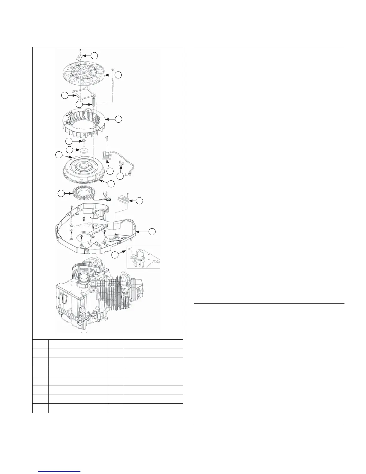
Flywheel/Ignition Components
N
M
L
O
K
J
H
I
G
E
F
A
C
D
B
A Special Washer B Debris Screen
C Stiffener D Hex Stud
E Fan F Flywheel Screw
G Washer H Ignition Module
I Wire Harness Clamp J Flywheel
K Magnet L Stator
M Rectifi er-Regulator N Backing Shroud
O Woodruff Key
Remove Ignition Modules
1. Rotate fl ywheel so magnet is away from modules.
2. Remove mounting screws and disconnect kill lead
from ignition modules. Note position of ignition
modules and wiring harness clip.
Remove Debris Screen and Cooling Fan
Remove screws, attaching hardware, and hex studs
securing debris screen, stiffener, and cooling fan to
fl ywheel.
Remove Flywheel
NOTE: Always use a fl ywheel strap wrench or holding
tool to hold fl ywheel when loosening or
tightening fl ywheel screw. Do not use any type
of bar or wedge to hold fl ywheel. Use of such
tools could cause fl ywheel to become cracked or
damaged.
NOTE: Always use a fl ywheel puller to remove fl ywheel
from crankshaft. Do not strike crankshaft or
fl ywheel, as these parts could become cracked
or damaged.
1. Use a fl ywheel strap wrench or holding tool to hold
fl ywheel and loosen screw securing fl ywheel to
crankshaft.
2. Remove screw and washer.
3. Use a puller to remove fl ywheel from crankshaft.
4. Remove woodruff key from crankshaft.
Inspection
Inspect fl ywheel for cracks and fl ywheel keyway for
damage. Replace fl ywheel if it is cracked. Replace
fl ywheel, crankshaft, and key if fl ywheel key is sheared
or keyway is damaged.
Inspect ring gear for cracks or damage. Kohler does not
provide ring gear as a serviceable part. Replace fl ywheel
if ring gear is damaged.
Remove Stator, Rectifi er-Regulator, and Wiring
Harness
1. Disconnect plug from rectifi er-regulator. If B+
(center) lead must be removed from plug, use a
small fl at tool to bend locking tang. Then remove
lead.
2. Remove mounting screws securing rectifi er-regulator
to backing shroud assembly. Note location of ground
lead. If rectifi er-regulator is not being replaced, it
may remain mounted to backing shroud assembly.
3. Remove screws securing stator to crankcase and
carefully separate stator wires from molded clips.
4. Unhook wiring harness from molded clips if it is
being serviced separately.
Remove Backing Shroud Assembly
Remove mounting screws securing backing shroud
assembly to crankcase.
Remove Spark Plugs
Remove spark plug from each cylinder head.