Repair
Exhaust gas aftertreatment system (depending on configuration)
Overview
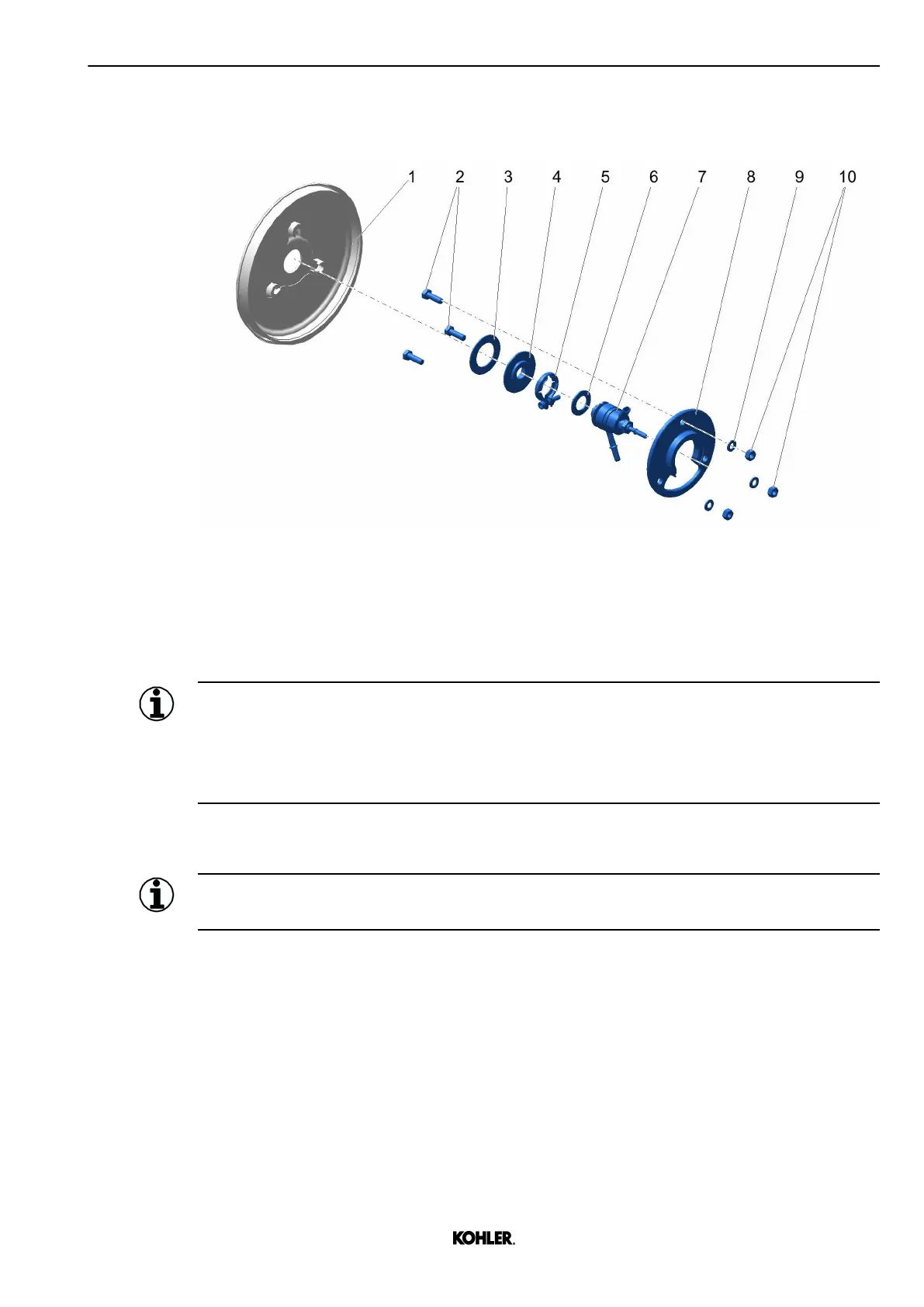
Fig. 267: Task overview
1
Dosing cover 6 Gasket
2 Screw (M8) 7 Diesel exhaust fluid injector
3 Gasket 8 Front mounting plate
4 Back mounting plate 9 Washer
5 V-clamp 10 Nut (M8)
Information
The design of the diesel exhaust fluid injector and its installation method may vary depending
on application.
Contact your nearest authorized Kohler service representative for up-to-date information about
the installation method.
Removal
Information
Always make sure that dust is prevented from going into the system.
KD62V12 33525088601_8_1 EN_US
2022-09
© 2022 by Kohler Co. All rights reserved.
247
 Loading...