Repair
Rocker arms
Valve set order
Information
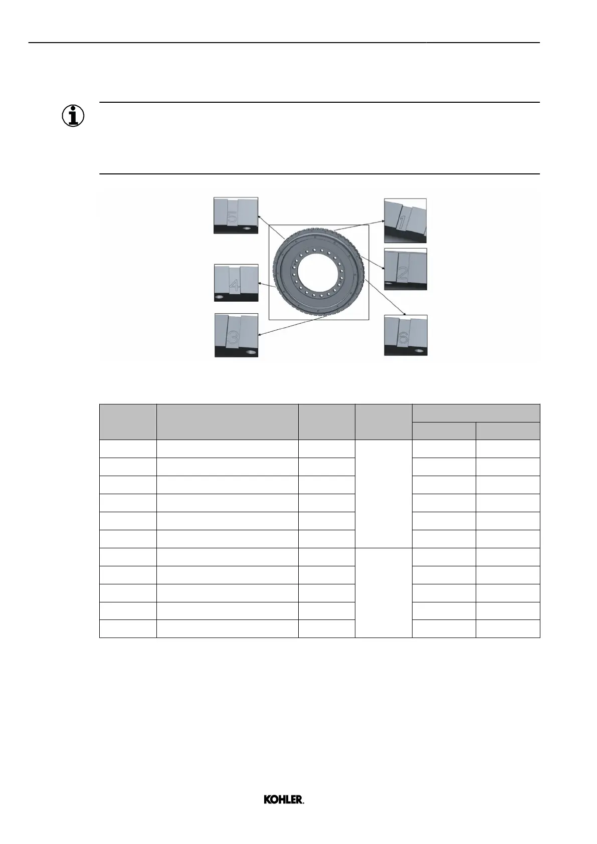
There is a marking on the flywheel to set the valve clearance.
The flywheel grooves 1 to 6 are identified in the picture below.
The valves must be set in the correct position for the matching cylinder.
Fig. 54: Flywheel marking
Step
Start point Groove N° Sequence
V12
Bank A Bank B
1 TDC overlap - A1 1
1st turn
No action No action
2 - 2 A5, A6 B5
3 - 6 No action No action
4 - 3 No action No action
5 - 4 A3 B1, B3
6 - 5 No action No action
7 TDC injection - A1 1
2nd turn
No action No action
8 - 2 A1, A2 B2
9 - 6 No action No action
10 - 3 No action No action
11 - 4 A4 B4, B6
Tab. 12: Reference table for the flywheel positioning
Set the valve clearance
Step 1
u Rotate crankshaft in direction of rotation with turning device to index 1.
70
© 2022 by Kohler Co. All rights reserved.
KD62V12 33525088601_8_1 EN_US
2022-09
 Loading...